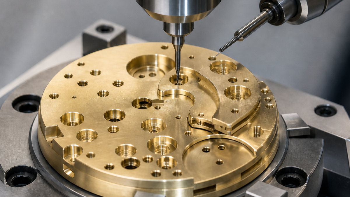
English: C360 Brass Watch Mainplate CNC Tool Selection for Jewel Seats and Thin Bridges
A C360 brass watch mainplate needs more than a collection of very small cutters. The decisive choices are how the pivot hole and jewel counterbore share one axis, how a 0.45 mm bridge remains supported, and how spindle runout is kept small relative to a Ø0.28 mm drill. This hypothetical route uses polished uncoated carbide, a two-diameter step reamer for the jewel seat, and a bonded carrier that remains in place until all fragile bridges are complete.
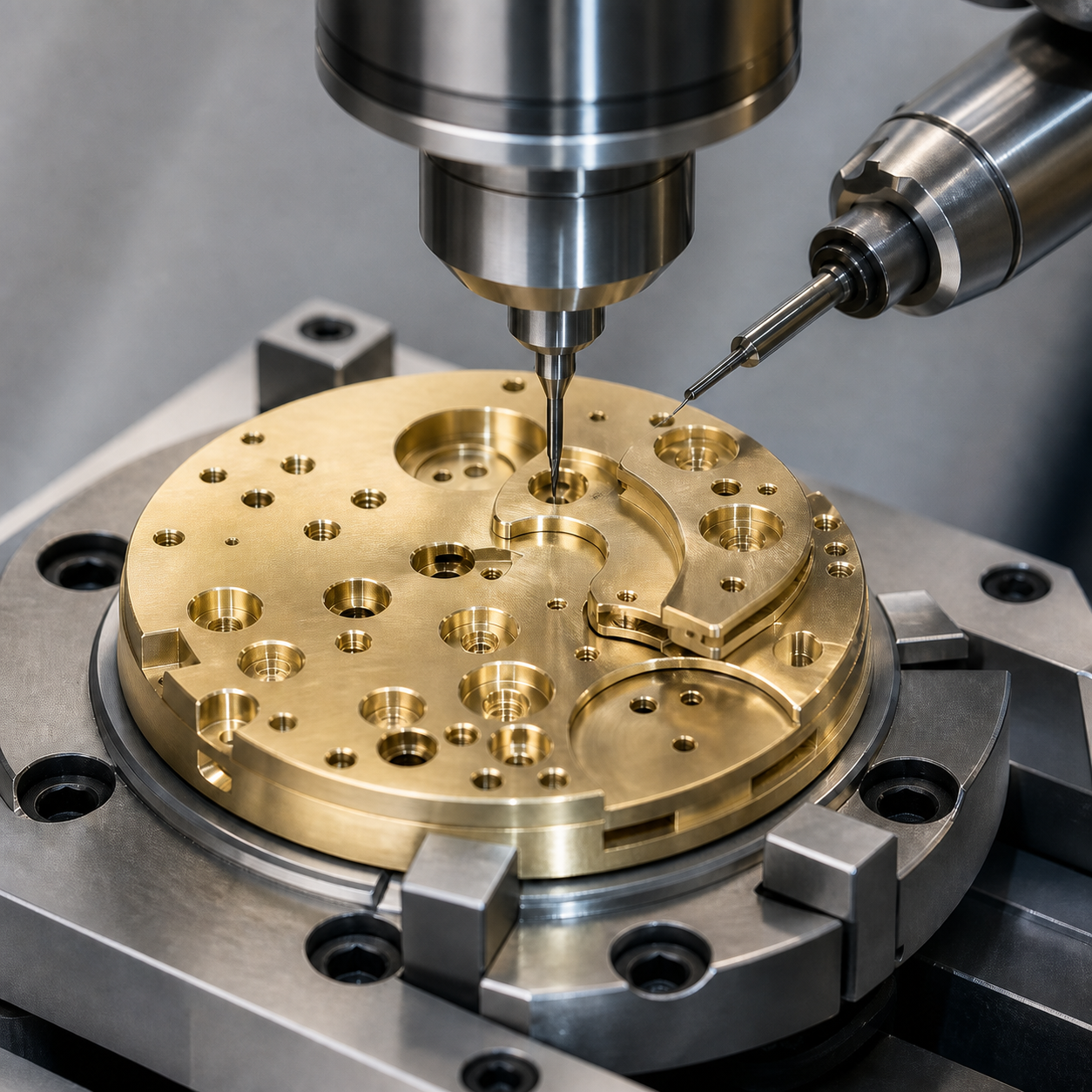
Drawing logic at watch scale
Lower face A, centre bore B and dowel C define the movement coordinate system. Eight jewel locations combine a Ø0.30 +0.005/0 mm pivot hole with a Ø1.50 H7 × 0.40 mm flat seat; concentricity between the two diameters is 0.008 mm. The centre bore is Ø6 H6, the escapement bridge is 0.45 ±0.020 mm thick, and a spring recess leaves a 0.30 mm floor. Jewel-seat floors require Ra 0.4 µm, while raised burrs around the pivots and any bow across A are prohibited.
The drawing is split into rigid features, supported thin features and free-state checks. Offsets measured while the mainplate is bonded are not reused after release.
Micro feature-to-tool decisions
| Feature | Selected tool, geometry and holder | Why this tool is used |
|---|---|---|
| Datum face and large recesses | Ø3 three-flute uncoated micrograin-carbide end mill, polished 35° helix, R0.1, 0.01 mm edge prep, HSK-E25 shrink holder | Short positive edges shear free-cutting brass; a coated steel cutter adds an unnecessary rounded edge. |
| Centre bore Ø6 H6 | Ø5.6 two-flute carbide drill, 130° split point, followed by a positive R0.1 micro-boring head on a 6 mm short bar | Fine boring corrects B position; a fixed reamer would follow drill drift. |
| Pivot and jewel seat | Ø0.28 two-flute uncoated polished-carbide drill, 118° thinned point, 1.2 mm flute length, followed by a custom Ø0.30/Ø1.50 four-flute solid-carbide step reamer with straight polished lands | Both diameters are generated on one axis; separate counterboring after repositioning risks eccentric jewel seats. |
| 0.45 mm bridge outline | Ø0.60 two-flute uncoated carbide end mill, 20° low helix, 1.0 mm cutting length, ultra-precision shrink collet | Low helix limits upward pull; a longer high-helix cutter can lift the bridge from the carrier. |
| Spring recess floor | Ø1.0 single-flute O-geometry polished carbide, R0.05, 0.8 mm cutting length | Large gullet clears short brass chips without rubbing the 0.30 mm floor. |
| M0.8 threaded holes | Ø0.62 two-flute carbide drill, then Ø0.55 single-row uncoated-carbide thread mill for M0.8×0.2, precision collet | Thread milling controls pitch diameter and avoids the breakage risk of a tiny tap. |
| Jewel-seat edge break | Ø1.5 four-flute uncoated carbide 90° chamfer mill, 0.03 mm programmed break | A brush can roll a burr into the pivot bore. |
Carrier strategy, toolpaths and burr control
The blank is bonded to a ground carrier outside the finished outline, then face A and the large recesses are roughed with 0.04 mm floor stock. The centre bore establishes B before the micro-hole array begins. Tool runout is measured at the Ø0.28 drill and limited to 0.002 mm; the first two jewel stations form a release gate for diameter, seat depth and concentricity.
Pivot drills enter once, maintain feed through the supported exit and are replaced by hole count rather than visual judgement. The bridge outline is roughed in shallow constant-engagement laps, leaving 0.03 mm on the wall; its finish pass occurs only after the neighbouring recesses are complete. Clean oil mist and vacuum remove chips. A bright burnished seat, rising spindle load or a feather burr triggers the tool-change rule.
Free-state inspection and FAQ
An optical CMM builds A-B-C and measures jewel-seat position without probe force. Qualified pins verify the pivot holes, a stepped plug checks the seat diameter and depth, and white-light metrology inspects the 0.45 mm bridge and Ra. After controlled carrier release, A flatness and the bridge height are measured again. No jewels are installed during machining inspection.
What tool keeps a jewel seat concentric to a pivot hole?
A solid-carbide step reamer that carries the Ø0.30 pilot and Ø1.50 seat on one body removes a second alignment error.
How much runout is acceptable for a 0.28 mm watch drill?
This hypothetical route limits measured runout to 0.002 mm; the qualified limit must remain small relative to the drill’s chip load and edge thickness.
Why is the thin bridge finished before debonding?
The carrier resists cutter lift and supports the 0.45 mm section until every adjacent pocket and edge is complete.
Related guides: micro-end-mill breakage control and holder runout at micron scale.
中文: C360黄铜钟表主夹板CNC配刀:宝石孔座与薄桥
C360钟表主夹板的难点不只是刀具直径小,而是Ø0.30轴尖孔和Ø1.50宝石座必须同轴、0.45 mm桥位不能被刀具上拉、Ø0.28钻头端跳必须与每齿进给相匹配。本案例用无涂层抛光硬质合金、同轴阶梯铰刀和全程保留的粘接载板来完成这些约束。
图纸的微小尺寸链
底面A、中心孔B和定位销C建立坐标。八处宝石位由Ø0.30 +0.005/0 mm轴孔及Ø1.50 H7×0.40 mm平底座组成,两径同心0.008 mm。中心孔Ø6 H6,擒纵桥厚0.45 ±0.020 mm,弹簧让位底厚0.30 mm;宝石座底Ra 0.4 µm,轴孔翻边和A面翘曲不允许。
微特征配刀表
| 特征 | 刀具与刀柄 | 配刀理由 |
|---|---|---|
| 基准面和大让位 | Ø3三刃无涂层细晶硬质合金,35°抛光槽,R0.1,刃口0.01 mm,HSK-E25热缩柄 | 正角锋刃剪切黄铜,无需钢件涂层刀的圆钝刃口。 |
| Ø6 H6中心孔 | Ø5.6双刃硬质合金钻、130°分割刃,随后R0.1正角微型精镗头,6 mm短杆 | 精镗修正B位置,铰刀只会跟随钻偏。 |
| 轴孔和宝石座 | Ø0.28双刃无涂层抛光微钻,118°薄钻尖、刃长1.2 mm;再用Ø0.30/Ø1.50四刃直槽抛光整体硬质合金阶梯铰刀 | 一次保持两径同轴,拒绝重新定位后单独沉座。 |
| 0.45 mm薄桥 | Ø0.60双刃无涂层硬质合金,20°低螺旋,刃长1.0 mm,超精热缩筒夹 | 低螺旋减少上拉力。 |
| 弹簧让位 | Ø1.0单刃O刃抛光硬质合金,R0.05,刃长0.8 mm | 大容屑槽避免在0.30 mm底面擦屑。 |
| M0.8螺纹 | Ø0.62双刃硬质合金钻+Ø0.55单排无涂层硬质合金螺纹铣刀,M0.8×0.2 | 可补偿中径,避免微型丝锥折断。 |
| 孔座倒钝 | Ø1.5四刃无涂层90°倒角刀,程序倒0.03 mm | 刷子会把软毛刺卷进轴孔。 |
载板、孔序和刀具寿命
毛坯在成品外粘到研磨载板上,A面和大让位底先留0.04 mm。中心孔先建立B,再加工微孔阵列。Ø0.28钻头在刀尖处实测端跳不超过0.002 mm,前两处宝石位先检孔径、座深和同轴后,才放行其余孔。
微钻一次进给穿过有支承的出口,并按孔数强制换刀。薄桥用恒定吃刀浅层开粗、侧壁留0.03 mm,邻近腔全部完成后才精桥。洁净油雾和真空排屑;孔座发亮、负载上升或出现羽状毛刺都必须停刀。
自由状态检验与问题
视觉三坐标建立A-B-C并测宝石座位置,合格针规测轴孔,阶梯塞规测座径和深度,白光测桥厚与Ra。载板受控释放后复测A面和平桥高度,机加工检验阶段不安装宝石。
宝石座和轴孔怎样保证同轴?
用同一刀体上的Ø0.30导向段和Ø1.50座径阶梯铰刀,取消第二次找正误差。
Ø0.28钻头端跳控制多少?
本路线实测上限为0.002 mm,实际合格值还要与每齿负载和刃厚能力匹配。
为什么薄桥要在脱胶前精加工?
载板抵消刀具上拉并支承0.45 mm截面,直到相邻腔和边缘全部完成。
Français: Outils CNC pour platine C360 : logements de rubis et ponts fins
La platine ne se résume pas à de petits diamètres. Le trou de pivot Ø0,30 et le logement Ø1,50 doivent partager le même axe, le pont de 0,45 mm doit rester soutenu et le faux-rond du foret Ø0,28 doit rester inférieur à sa charge utile. Un carbure poli non revêtu, un alésoir étagé et un support collé répondent à ces trois contraintes.
Références du plan
A, l’alésage central B et la goupille C définissent le mouvement. Huit positions combinent Ø0,30 +0,005/0 mm et un siège Ø1,50 H7×0,40 mm, concentriques à 0,008 mm. B est Ø6 H6; le pont mesure 0,45 ±0,020 mm et le fond de ressort 0,30 mm. Le siège impose Ra 0,4 µm sans bavure relevée.
Choix des micro-outils
| Fonction | Outil | Décision |
|---|---|---|
| Face et poches | Ø3, trois dents carbure non revêtu, goujures polies 35°, R0,1, arête 0,01 mm, HSK-E25 fretté | Coupe positive du laiton. |
| Centre Ø6 H6 | Foret Ø5,6 à 130°, puis micro-alésage positif R0,1 | Corrige la position B. |
| Pivot et rubis | Foret Ø0,28 poli, pointe amincie 118°, puis alésoir carbure étagé Ø0,30/Ø1,50 à quatre goujures droites | Deux diamètres sur un seul axe. |
| Pont | Ø0,60, deux dents, hélice basse 20°, coupe 1,0 mm | Faible traction verticale. |
| Logement ressort | Ø1,0, une dent O polie, R0,05 | Évacue les copeaux du fond mince. |
| Filetage M0,8 | Foret Ø0,62 puis fraise à fileter carbure Ø0,55 à rangée unique | Évite un taraud cassé. |
| Cassé | Ø1,5, quatre dents, 90°, cassé 0,03 mm | Pas de brossage du pivot. |
Support et contrôle
La pièce reste collée sur une plaque rectifiée. B est créé avant le réseau; le faux-rond du foret est limité à 0,002 mm. Deux premiers sièges sont mesurés avant la série. Le pont est ébauché par faibles engagements et fini après les cavités voisines. Une brillance, une charge montante ou une bavure plumeuse retire l’outil.
La vision contrôle A-B-C, des piges vérifient les pivots et un calibre étagé mesure le siège. La lumière blanche mesure pont et Ra; A est reprise après décollage.
Comment garder pivot et siège coaxiaux?
Avec un alésoir étagé portant les deux diamètres.
Quel faux-rond pour Ø0,28?
Ici 0,002 mm mesuré à l’arête.
Pourquoi finir le pont sur support?
Le collage oppose la traction de la fraise.
Voir les microfraises et le faux-rond des porte-outils.
Русский: Инструмент для платины C360: камневые гнёзда и мосты
Для часовой платины важны не только малые диаметры. Отверстие оси Ø0,30 и гнездо Ø1,50 должны иметь одну ось, мост 0,45 мм — оставаться на опоре, а биение сверла Ø0,28 — быть меньше полезной нагрузки кромки. Применяются полированный непокрытый карбид, ступенчатая развёртка и приклеенная плита.
Размерная схема
Плоскость A, центральное отверстие B и штифт C задают координаты. Восьми позициям назначены Ø0,30 +0,005/0 мм и плоское гнездо Ø1,50 H7×0,40 мм при соосности 0,008 мм. B — Ø6 H6, мост — 0,45 ±0,020 мм, дно выборки — 0,30 мм. Гнездо требует Ra 0,4 мкм.
Таблица микроинструмента
| Элемент | Инструмент | Причина |
|---|---|---|
| Плоскость | Ø3, три зуба, непокрытый карбид, полированные 35°, R0,1, кромка 0,01 мм, HSK-E25 | Остро режет латунь. |
| Центр Ø6 H6 | Сверло Ø5,6, 130°, затем микрорезец R0,1 | Исправляет B. |
| Ось и камень | Сверло Ø0,28, 118°, затем четырёхзубая ступенчатая развёртка Ø0,30/Ø1,50 | Два диаметра на одной оси. |
| Мост | Ø0,60, два зуба, малая спираль 20°, длина 1,0 мм | Не поднимает тонкую часть. |
| Выборка | Ø1,0, один полированный O-зуб, R0,05 | Свободный выход стружки. |
| M0,8 | Сверло Ø0,62 и однорядная резьбовая фреза Ø0,55 | Нет риска сломанного метчика. |
| Фаска | Ø1,5, четыре зуба, 90°, 0,03 мм | Не завальцовывает ось. |
Маршрут и измерение
Заготовка приклеена к шлифованному носителю. После B обрабатывается сетка; биение Ø0,28 ограничено 0,002 мм. Два первых гнезда проверяются до серии. Мост режется малыми зацеплениями и заканчивается после соседних карманов. Блеск, рост нагрузки или перистый заусенец означают смену инструмента.
Оптическая КИМ измеряет A-B-C, штифты — отверстия, ступенчатый калибр — гнёзда. Белый свет проверяет мост и Ra, после отклейки повторяется A.
Как сохранить общую ось?
Ступенчатой развёрткой Ø0,30/Ø1,50.
Какое биение у сверла?
В этом маршруте не более 0,002 мм.
Зачем опора под мостом?
Она воспринимает подъёмную силу фрезы.
См. микрофрезы и биение держателя.


