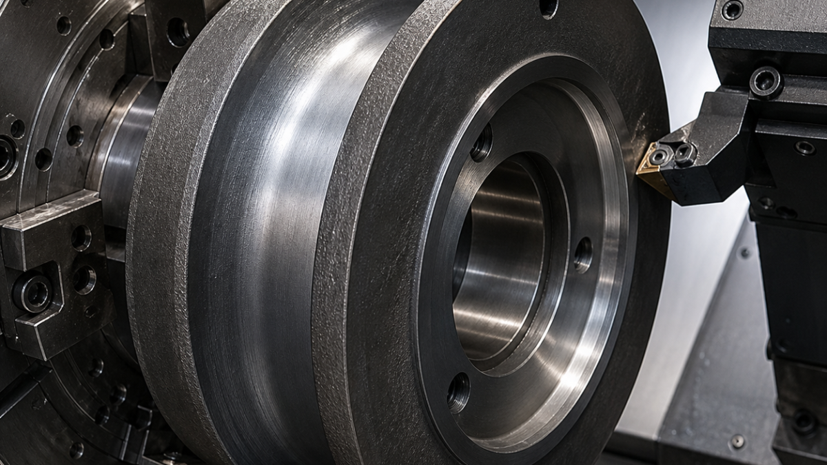
English: AISI 4340 Wire-Rope Sheave CNC Tool Selection for U-Groove Profile and Bearing Bore
The decisive tooling problem on an AISI 4340 wire-rope sheave is not simply turning a large groove. The U-groove centreline, two bearing seats and side-face runout must all refer to one axis after the quenched-and-tempered forging is unclamped. A rough-bore-first route, an expanding mandrel, supported round-carbide profiling inserts and a separate precision boring head make that relationship controllable in this hypothetical case.
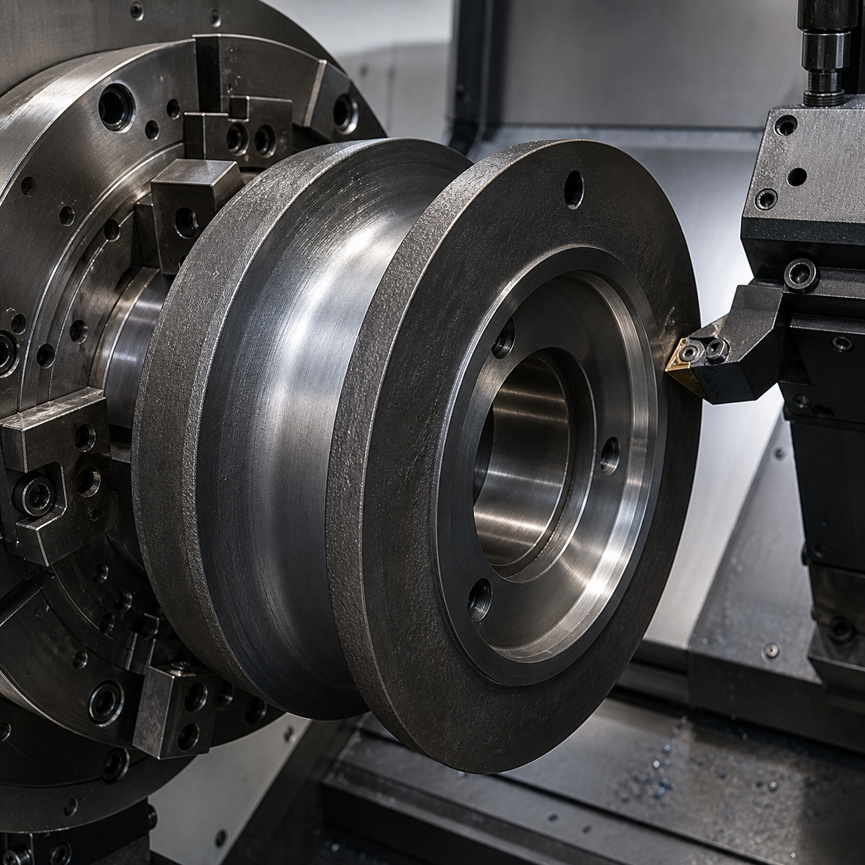
Build the drawing around the rope path
The sheave is Ø420 mm overall and 58 mm wide. Datum bore A is Ø100 H7 with two Ø118 H8 × 12 mm bearing counterbores; side face B controls axial location, and the lubrication cross-hole defines clock datum C. The rope groove has a 13.0 ±0.05 mm root radius, 25.8 ±0.08 mm opening, 22.0 ±0.10 mm depth and Ra 1.6 µm. Groove centre offset from B is 29.00 ±0.04 mm, groove radial runout to A is 0.040 mm, and each side face must run within 0.030 mm to the bearing axis.
The material note for this route is AISI 4340 quenched and tempered to a hypothetical 32–36 HRC before final machining. Hardness uniformity and forging scale are checked before committing the finishing edges. Any magnetic-particle or other safety-critical examination remains governed by the product specification; it is not invented by this machining example.
Cutting sequence matched to radial load
| Operation | Tool package | Load-management rationale |
|---|---|---|
| Forged faces and rim roughing | CNMG 120412 ISO-P25 CVD TiCN/Al2O3 carbide, heavy chipbreaker, R1.2, Capto C8 holder | The strong edge removes scale at stable depth. A sharp PVD finishing insert would chip before reaching uniform material. |
| Prebore A | Ø80 indexable carbide drill with four ISO-P30 inserts, 2×D body, followed by a twin-cartridge rough-boring head with R0.8 inserts | Balanced cutting leaves 0.35 mm radial stock. Single-point deep boring at this stage would amplify forging eccentricity. |
| Side faces B and opposite face | WNMG 080408 ISO-P15 CVD carbide with 1.5 mm wiper flat, neutral lead, rigid face-turn holder | The wiper holds Ra 1.6 µm at useful feed; alternating light passes equalize residual stress before mandrel mounting. |
| U-groove volume roughing | RCMT 1204 round ISO-P25 PVD-AlTiN carbide, positive ground chipformer, R6 circular edge, reinforced top-clamp holder | Programmed copy turning spreads contact around the round insert. A full-width 25.8 mm form tool would create excessive radial force and trap chips. |
| Groove semifinish | RCGT 1003 precision-ground positive carbide, fine-grain P20 substrate, AlTiN, 6 µm edge hone, R5 profile, damped modular holder | Smaller contact arc resolves both flanks and root with 0.15 mm stock. A negative round insert would push the rim away from A. |
| Groove finish | Two matched RCGT 0803 PVD-AlCrN carbide inserts, R4, polished rake, 4 µm hone; one dedicated to left flank/root and one to right flank/root | Splitting the finish limits engagement and lets wear compensation preserve the 13.0 mm root radius. One broad custom form insert is rejected for force and chatter. |
| Ø100 H7 and Ø118 H8 seats | Adjustable two-edge fine-boring head with ISO-P10 cermet-grade carbide cartridges, R0.2 and wiper land, short HSK-A100 arbor | The bore and counterbores are corrected on the same axis. A long reamer cannot independently correct two bearing seats. |
| Ø6 lubrication cross-hole and entry break | Ø6 three-flute through-coolant solid-carbide drill, 140° split point, AlTiN, 5×D; Ø8 four-flute 90° carbide chamfer mill | Through coolant clears the radial chip column. A pecking HSS drill would repeatedly rub the 32–36 HRC wall. |
| Internal cross-hole breakout | Ø10 four-tooth PVD-carbide reverse chamfer head, 45°, slim modular shank | It removes the bore-side lip without hand grinding near the bearing seat. |
Datum transfer from jaws to the finished bore
In the first setup, three soft jaws grip a qualified forged band. Both faces are alternately skimmed, the rim is roughed, and A is prebored while 0.35 mm remains. The sheave is unclamped for a thermal and stress pause. A second setup locates on the semifinished bore with a long expanding mandrel and pulls B against three axial pads; clamp pressure is qualified by comparing bore roundness before and after release.
The U-groove is opened in radial layers with the RCMT insert. Each path starts on a flank and exits away from the root so chips do not pack at the lowest point. Semifinish leaves 0.15 mm normal stock across the profile. Finish uses matched left and right inserts in alternating passes; the root is blended only after both flank angles and opening width are in tolerance. Constant surface speed is capped at the groove root to maintain torque margin.
Coolant jets enter from both sides of the groove and a lower nozzle clears the root. A repeating waviness at the sheave’s natural frequency, notch wear at the maximum contact line, loss of opening width or a load spike in the root triggers tool replacement. The finishing insert is never used to erase a roughing chatter band because that transfers an unknown profile error into the final radius.
Inspection follows the bearing axis
A bore gauge and roundness instrument qualify Ø100 H7 and both counterbores. On a calibrated inspection arbor, a scanning probe measures groove radius, opening and centre offset while a radial indicator records runout through 360°. Side faces are checked to the same arbor, and a borescope confirms the internal cross-hole edge. Surface roughness is sampled on both flanks and the root because a single accessible trace can miss tool pull-off.
Why machine the wire-rope groove after establishing the bore?
The expanding mandrel makes the bearing axis the machining axis, so groove runout is controlled directly rather than inherited from the rough forging OD.
Should a full-profile form tool finish the U-groove?
Not in this route. Splitting the left flank, root and right flank across supported round inserts reduces radial force and allows profile compensation.
How is chatter detected on a large 4340 sheave?
Combine spindle-load and vibration trends with a profile scan; periodic waviness or a load peak at the root is a tool-and-stability signal, not a surface to polish away.
Related guidance: fixture and chatter control and reading carbide wear signatures.


