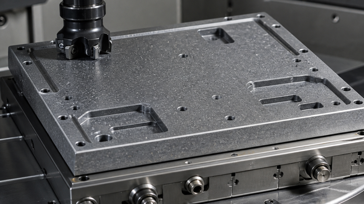
English: AlSiC Power-Module Baseplate CNC Tool Selection for Thermal Flatness and Insert Bores
An AlSiC power-module baseplate needs a tooling split between abrasive bulk removal and the final thermal-interface face. The practical long-tail answer is to rough pockets with diamond-coated carbide, generate the broad datum with a low-runout PCD face mill, and finish insert bores with dedicated PCD sizing tools while the plate rests on defined pads. This hypothetical case keeps the 0.025 mm flatness requirement separate from clamped machine coordinates and prevents silicon-carbide particles from becoming a second cutting edge.
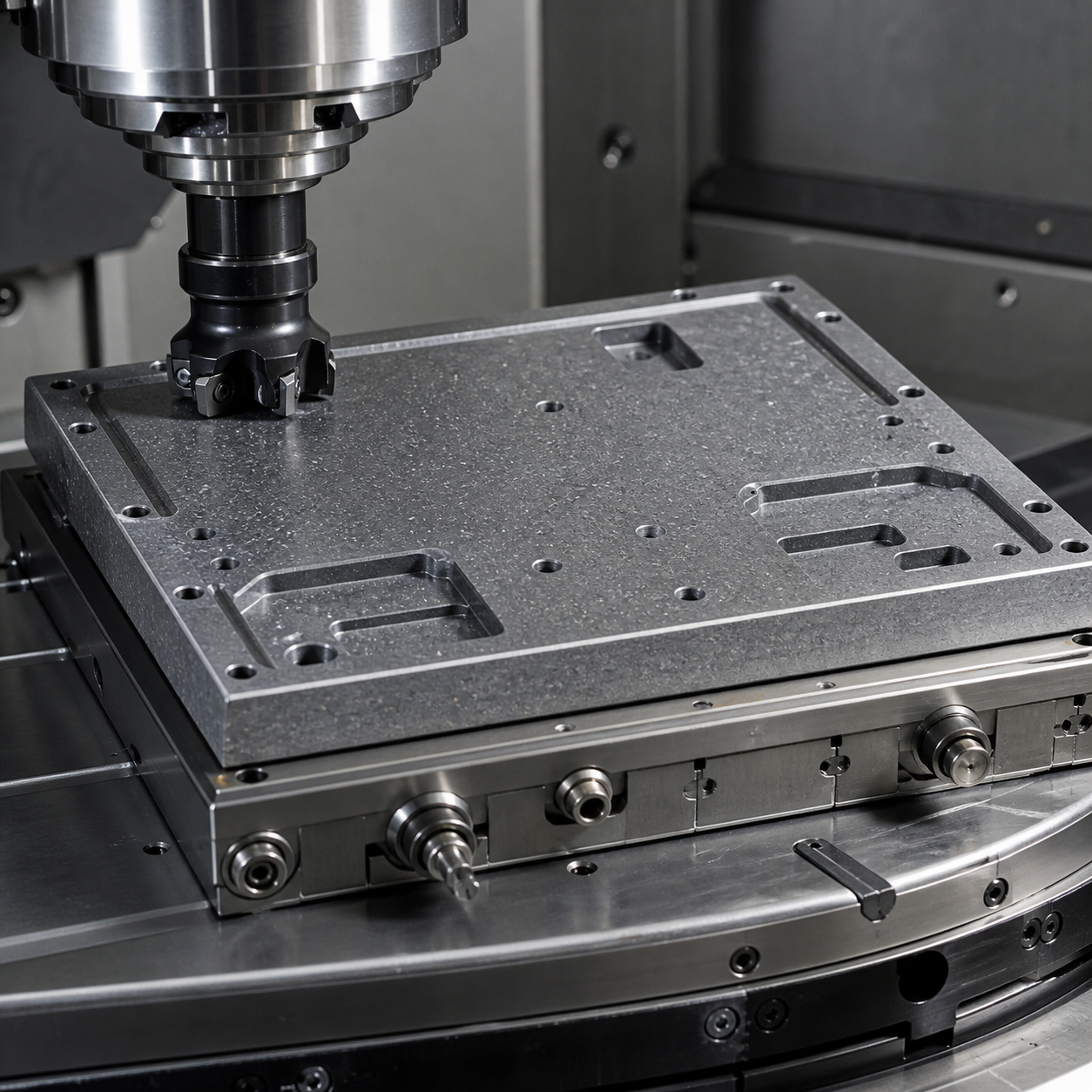
Functional surfaces, not just a rectangular plate
The lower thermal face A is 160 × 120 mm and must be flat within 0.025 mm after release, with Ra 0.8 µm and no isolated pull-out larger than the drawing acceptance sample. Two dowel bores B and C define module orientation. The opposite side contains four isolation pockets 2.00 ±0.03 mm deep, a 1.20 mm perimeter sealing land, twelve Ø5 H7 bores for pressed thread inserts, and four Ø6 H8 coolant-manifold locations. Remaining web thickness under a pocket is 3.00 ±0.05 mm; parallelism of the pocket floors to A is 0.030 mm.
AlSiC is an aluminium matrix loaded with hard silicon-carbide particles. The exact fraction, particle size and heat-treatment state belong on the material certificate because they change edge wear and pull-out. The route below qualifies tools against the supplied lot rather than assuming that every AlSiC grade cuts identically.
Tool card for each surface class
| Surface class | Selected cutter, edge and holder | Use limit and rejected choice |
|---|---|---|
| Stock face and outside profile | Ø12 two-flute diamond-coated fine-grain carbide end mill, 30° helix, R0.3, 18 mm flute length, balanced shrink-fit holder | The coating protects carbide from SiC abrasion while the two large gullets evacuate mixed chips. An uncoated aluminium end mill loses diameter too quickly. |
| Isolation-pocket roughing | Ø8 three-flute diamond-coated carbide, unequal pitch, R0.5, 12 mm reach, through-air hydraulic chuck | Helical entry and constant engagement keep particles moving. A high-feed insert mill is rejected because its minimum corner radius cannot protect the 1.20 mm sealing land. |
| Pocket walls and 1.5 mm internal corners | Ø3 four-flute diamond-coated carbide, 25° helix, R0.15, 7 mm flute length, ultra-short heat-shrink extension | Four supported edges finish the abrasive wall. A longer microtool would trade useful reach for runout and taper. |
| Thermal face A | Ø63 five-pocket PCD face mill, axial runout set below 0.003 mm, 0.05 mm wiper flats, HSK-A63 face-contact arbor | One light climb pass creates a consistent lay. A carbide face mill can meet size initially but its changing flank wear prints steps across 160 mm. |
| Ø5 H7 insert bores | Ø4.7 diamond-coated carbide drill, 140° point and through coolant; then Ø5 six-flute PCD-tipped straight reamer, 6 µm edge preparation, hydraulic holder | The reamer sets press-fit size after abrasive drilling. Circular interpolation is rejected because cutter wear would make twelve different diameters. |
| Ø6 H8 manifold locations | Ø5.6 PCD-veined carbide drill followed by an adjustable PCD fine-boring cartridge, R0.1, short modular head | Fine boring corrects position and diameter. A fixed reamer could follow a particle-deflected pilot. |
| Counterbores and 0.15 mm edge breaks | Ø9 three-flute diamond-coated carbide counterbore with integral pilot; Ø6 two-flute 90° PCD chamfer tool | A piloted tool controls insert-seat squareness. Abrasive hand deburring can round the sealing land and contaminate A. |
Two supports for two different questions
During pocket roughing, the blank sits on three hardened pads beneath thick regions and is restrained by low-force perimeter clamps. Floors are left 0.08 mm high, walls 0.05 mm heavy. The toolpath begins in the deepest central volume and works outward so remaining webs stay supported. The part is then released, cleaned and allowed to equalize at the inspection temperature before its natural bow is mapped.
For A finishing, the plate is inverted onto a vacuum fixture whose lands coincide with the drawing’s stiff zones; vacuum level is limited by a deflection trial rather than maximized. A PCD face-mill test strip at one edge confirms wiper height and pull-out before the full pass. Insert bores are made after A establishes Z, but pressed inserts are not installed until all machining and cleanliness checks are complete.
Dry point extraction or a validated wet-capture method must prevent abrasive chips from recirculating through the spindle and guideways. A rising spindle-load slope, loss of corner radius, gray smear on the PCD land or increasing bore thrust ends tool life. Tools are not run until catastrophic chipping because one missing edge can scratch the entire thermal face.
Inspection tied to temperature and support
A calibrated surface plate and scanning probe measure free-state A at the specified temperature. White-light metrology checks Ra and pull-out against the agreed sample; a CMM builds A-B-C, pocket depth, web thickness and bore position. Air or certified plug gauges verify the insert bores, while a low-force fixture repeats A under assembly-like support to distinguish true shape from mounting response. Results record material lot and PCD edge number so abrasive variation is traceable.
What cutter gives the best flat AlSiC thermal face?
A low-runout PCD face mill with matched wiper flats is preferred for the final broad pass; its setup must be qualified on the actual AlSiC lot.
Why not finish the insert bores by end-mill interpolation?
Diameter loss on an abrasive composite changes every interpolated hole. A dedicated PCD reamer or fine-boring head makes wear measurable and correctable.
Should AlSiC be machined dry or wet?
The choice belongs to the machine, material and exposure-control assessment. Either method must capture abrasive particulate and prevent recirculation; an open uncontrolled dust stream is not acceptable.
Related reading: PCD tool selection for aluminium systems and runout control for precision cutters.


