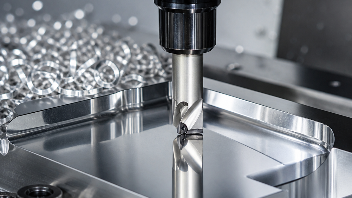
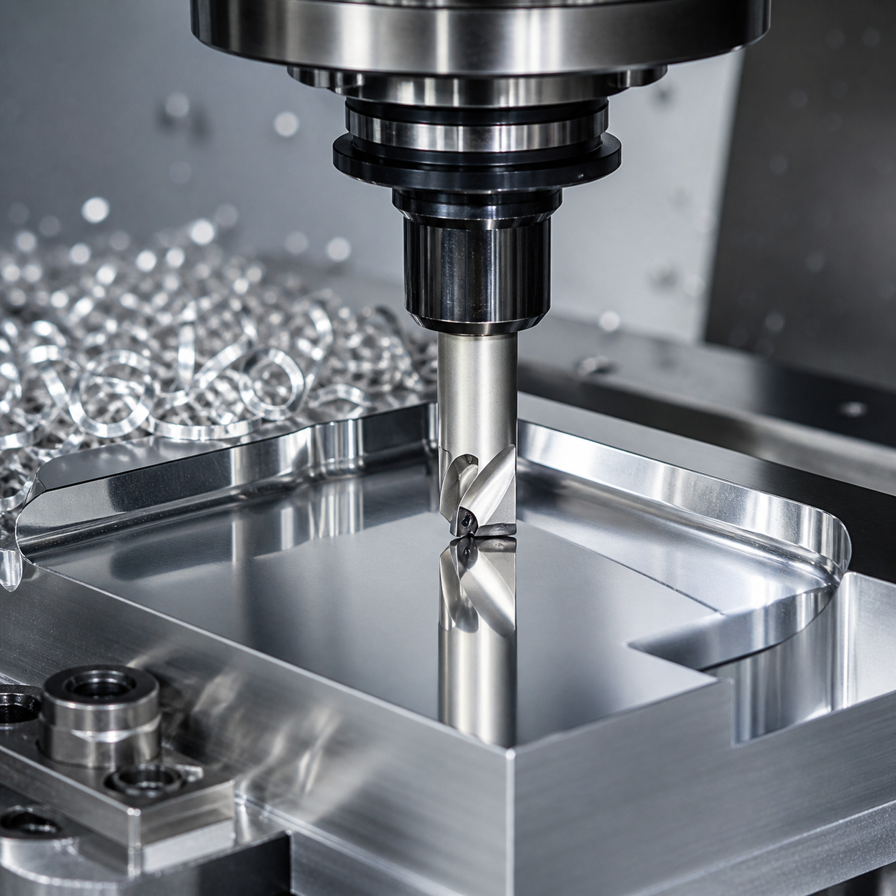
English: PCD Tool Selection for Aluminum Mirror Finishing and Abrasive Alloys
PCD is selected for abrasion resistance and a very sharp stable edge, not because every aluminum surface needs diamond. It is valuable on high-silicon aluminum, graphite and abrasive non-ferrous materials, and for long runs of sealing lands. A sharp uncoated carbide tool can be better for interrupted low-volume work or features that need a smaller, more flexible geometry.
For a low-volume aluminum part whose thin ribs make cutting force more important than abrasive life, compare the APGT1604 polished-carbide rib-milling case before specifying PCD. Its decision rests on a sharp positive edge, chip escape and rib support; the trial must still verify released wall thickness and burrs rather than judging the tool only by surface brightness.
Match the PCD edge to the surface function
A face-milling wiper insert controls broad flatness and feed marks; a tipped end mill reaches walls and shoulders; a PCD reamer or boring tool controls a stable bore. Specify positive rake for low cutting force, minimum edge hone compatible with strength, and enough polished chip space. Reject PCD for ferrous cutting at normal temperature because chemical wear can be rapid.
| Feature / risk | Tool decision | Rejected alternative | Inspection |
|---|---|---|---|
| Broad sealing land | PCD face mill with wiper, balanced arbor | Ball nose polishing path | Flatness, waviness, contact |
| High-silicon bore | PCD boring/reaming edge, positive rake | Uncoated carbide for long series | Size, roundness, finish |
| Interrupted casting skin | Sacrificial carbide first; PCD after stock is continuous | PCD impact through skin | Microchips at edge |
| Ferrous insert crossing | Separate tool/path and stop PCD before iron | PCD across steel insert | Material boundary and burr |
Protect the edge and the datum
Use a balanced arbor or low-runout hydraulic/shrink holder and measure the cutting edge, not only the shank. Remove casting skin and interrupted stock with a sacrificial tool when impact risk is high. Keep chips from crossing the finished land, maintain one continuous finish pass and avoid hand blending a functional seal surface.
Inspect function rather than shine
Measure flatness, bore size, waviness and Ra with a method suited to the drawing. A mirror appearance can hide long-wave error, smeared aluminum or a step at the toolpath join. Track edge notching, microchips, built-up material and finish trend. Clean with a non-scratching method before leak, blue-check or contact-pattern inspection.
Related decision paths: coating selection guide; aluminum finishing guide; wiper geometry guide.
PCD questions
PCD for all aluminum? No; volume, silicon, abrasion and surface function must justify it. Coolant or dry? Use the stable method that evacuates chips and avoids thermal shock for the tool system. Can PCD cut steel? It is generally rejected for conventional ferrous machining; CBN or coated carbide is normally considered.


