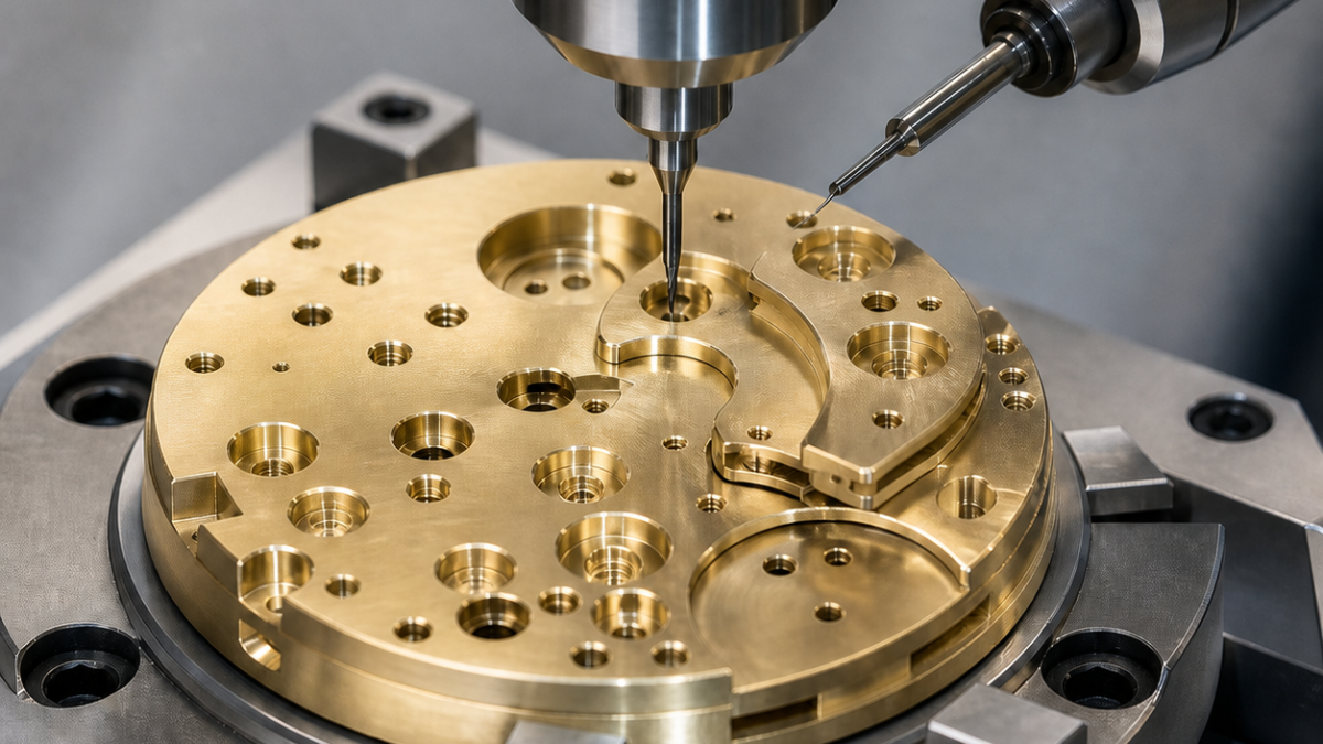
English: C360 Brass Watch Mainplate CNC Tool Selection for Jewel Seats and Thin Bridges
A C360 brass watch mainplate needs more than a collection of very small cutters. The decisive choices are how the pivot hole and jewel counterbore share one axis, how a 0.45 mm bridge remains supported, and how spindle runout is kept small relative to a Ø0.28 mm drill. This hypothetical route uses polished uncoated carbide, a two-diameter step reamer for the jewel seat, and a bonded carrier that remains in place until all fragile bridges are complete.
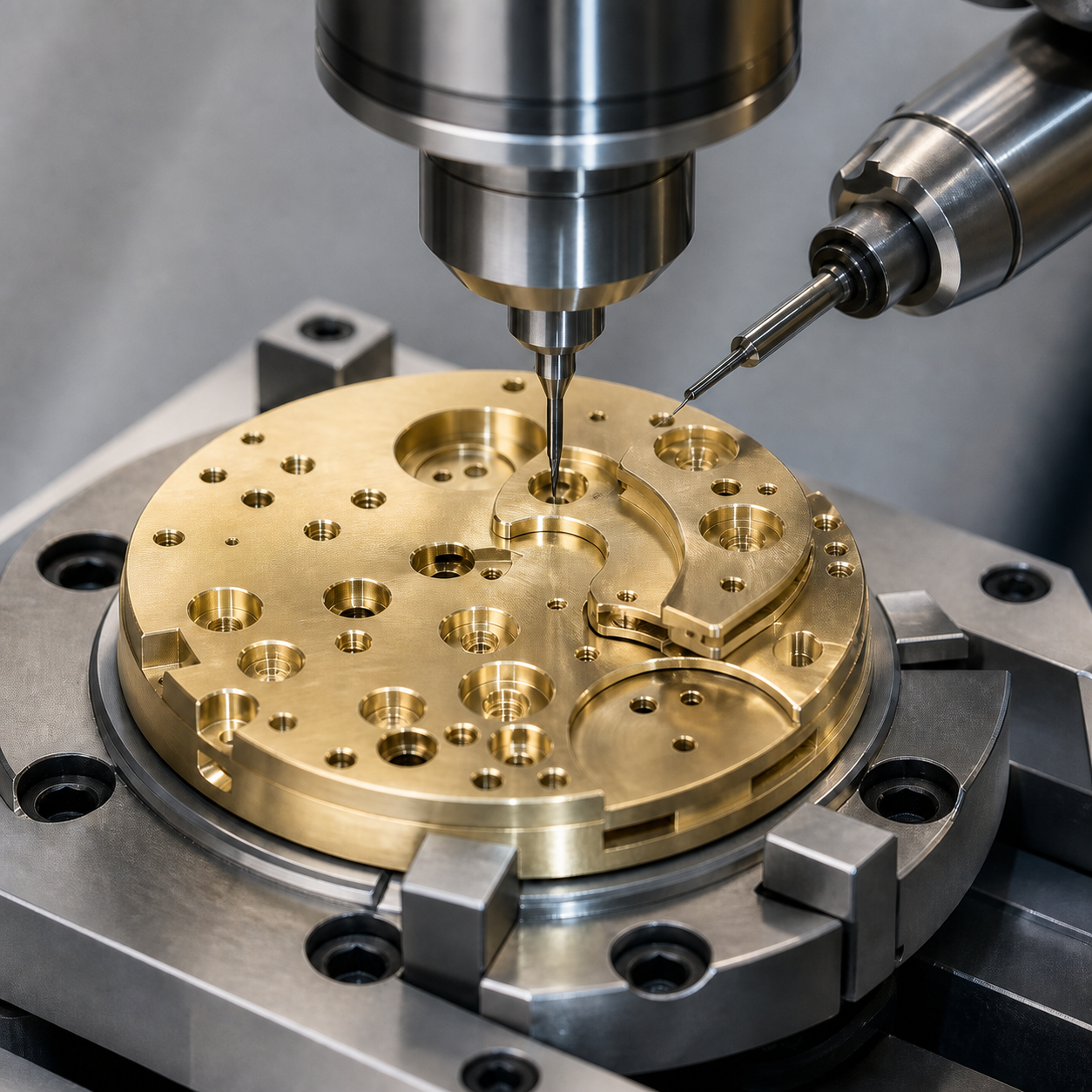
Drawing logic at watch scale
Lower face A, centre bore B and dowel C define the movement coordinate system. Eight jewel locations combine a Ø0.30 +0.005/0 mm pivot hole with a Ø1.50 H7 × 0.40 mm flat seat; concentricity between the two diameters is 0.008 mm. The centre bore is Ø6 H6, the escapement bridge is 0.45 ±0.020 mm thick, and a spring recess leaves a 0.30 mm floor. Jewel-seat floors require Ra 0.4 µm, while raised burrs around the pivots and any bow across A are prohibited.
The drawing is split into rigid features, supported thin features and free-state checks. Offsets measured while the mainplate is bonded are not reused after release.
Micro feature-to-tool decisions
| Feature | Selected tool, geometry and holder | Why this tool is used |
|---|---|---|
| Datum face and large recesses | Ø3 three-flute uncoated micrograin-carbide end mill, polished 35° helix, R0.1, 0.01 mm edge prep, HSK-E25 shrink holder | Short positive edges shear free-cutting brass; a coated steel cutter adds an unnecessary rounded edge. |
| Centre bore Ø6 H6 | Ø5.6 two-flute carbide drill, 130° split point, followed by a positive R0.1 micro-boring head on a 6 mm short bar | Fine boring corrects B position; a fixed reamer would follow drill drift. |
| Pivot and jewel seat | Ø0.28 two-flute uncoated polished-carbide drill, 118° thinned point, 1.2 mm flute length, followed by a custom Ø0.30/Ø1.50 four-flute solid-carbide step reamer with straight polished lands | Both diameters are generated on one axis; separate counterboring after repositioning risks eccentric jewel seats. |
| 0.45 mm bridge outline | Ø0.60 two-flute uncoated carbide end mill, 20° low helix, 1.0 mm cutting length, ultra-precision shrink collet | Low helix limits upward pull; a longer high-helix cutter can lift the bridge from the carrier. |
| Spring recess floor | Ø1.0 single-flute O-geometry polished carbide, R0.05, 0.8 mm cutting length | Large gullet clears short brass chips without rubbing the 0.30 mm floor. |
| M0.8 threaded holes | Ø0.62 two-flute carbide drill, then Ø0.55 single-row uncoated-carbide thread mill for M0.8×0.2, precision collet | Thread milling controls pitch diameter and avoids the breakage risk of a tiny tap. |
| Jewel-seat edge break | Ø1.5 four-flute uncoated carbide 90° chamfer mill, 0.03 mm programmed break | A brush can roll a burr into the pivot bore. |
Carrier strategy, toolpaths and burr control
The blank is bonded to a ground carrier outside the finished outline, then face A and the large recesses are roughed with 0.04 mm floor stock. The centre bore establishes B before the micro-hole array begins. Tool runout is measured at the Ø0.28 drill and limited to 0.002 mm; the first two jewel stations form a release gate for diameter, seat depth and concentricity.
Pivot drills enter once, maintain feed through the supported exit and are replaced by hole count rather than visual judgement. The bridge outline is roughed in shallow constant-engagement laps, leaving 0.03 mm on the wall; its finish pass occurs only after the neighbouring recesses are complete. Clean oil mist and vacuum remove chips. A bright burnished seat, rising spindle load or a feather burr triggers the tool-change rule.
Free-state inspection and FAQ
An optical CMM builds A-B-C and measures jewel-seat position without probe force. Qualified pins verify the pivot holes, a stepped plug checks the seat diameter and depth, and white-light metrology inspects the 0.45 mm bridge and Ra. After controlled carrier release, A flatness and the bridge height are measured again. No jewels are installed during machining inspection.
What tool keeps a jewel seat concentric to a pivot hole?
A solid-carbide step reamer that carries the Ø0.30 pilot and Ø1.50 seat on one body removes a second alignment error.
How much runout is acceptable for a 0.28 mm watch drill?
This hypothetical route limits measured runout to 0.002 mm; the qualified limit must remain small relative to the drill’s chip load and edge thickness.
Why is the thin bridge finished before debonding?
The carrier resists cutter lift and supports the 0.45 mm section until every adjacent pocket and edge is complete.
Related guides: micro-end-mill breakage control and holder runout at micron scale.


