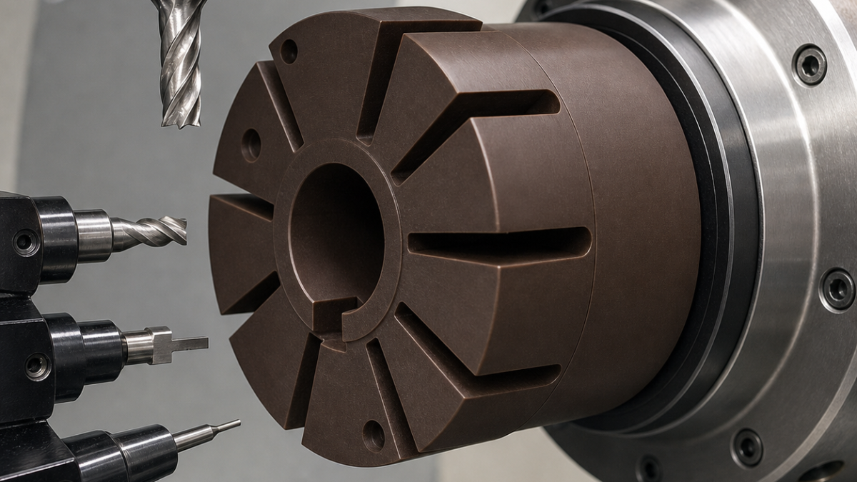
English: Vespel SP-1 Rotor CNC Tool Selection for Vane Slots and Seal Lands
A Vespel SP-1 vacuum-pump rotor stays accurate when heat and clamping are treated as dimensions. The bore and seal lands are turned with sharp polished carbide on a soft mandrel; eight vane slots are opened symmetrically with a single-flute O-geometry cutter; and balancing pockets are delayed until free-state runout is known. This hypothetical route avoids polishing a warm, expanded rotor to the wrong size.
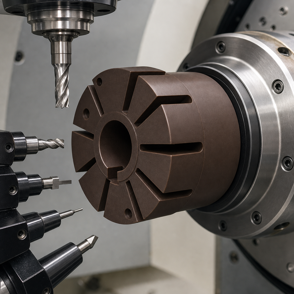
Drawing conditions and stabilization rule
Bore A and face B locate the rotor; keyway C clocks eight 3.00 +0.03/0 mm vane slots. Seal-land runout is 0.020 mm, face flatness 0.025 mm and bore finish Ra 0.8 µm. Slot floors require R0.4 and edges a 0.10 mm break. Blank, fixture and gauges stabilize at the drawing temperature before finish offsets are accepted.
Tool map for a low-force rotor
| Feature | Selected tool and holder | Rejected alternative |
|---|---|---|
| Faces and seal lands | Ground DCGT 11T304 uncoated micrograin carbide, polished rake, R0.4, positive holder | A honed coated steel insert rubs and heats the polymer. |
| Precision bore | Positive polished carbide fine-boring insert R0.2 on a short modular bar | A reamer can size the warm bore but cannot correct mandrel-related taper. |
| Vane-slot roughing | Ø2.5 single-flute uncoated carbide O-flute, 15° helix, 14 mm cut, hydraulic holder | Large gullet evacuates stringy chips; a four-flute cutter packs them. |
| Slot-wall finish | Ø3 three-flute polished carbide, unequal pitch, R0.2, short reduced neck | Finishes both walls by compensation; a 3 mm form tool cannot correct wear independently. |
| Keyway | Ø2 two-flute straight polished carbide, 5 mm cut, micro chuck | Straight flute limits axial pull at the bore. |
| Balance pockets | Ø6 single-flute polished carbide, flat end, minimum projection | Clean measurable removal after runout data; abrasive hand correction is uncontrolled. |
| Edge break | Ø8 single-flute polished 90° carbide chamfer tool | Programs 0.10 mm without smearing a manual scraper. |
Symmetric slot release and chip behavior
The blank is faced and bored in soft jaws, then located on a close-fit expanding polymer mandrel whose torque is recorded. Slots are machined in opposite pairs 1–5, 3–7, 2–6, 4–8. The O-flute rougher leaves 0.15 mm per wall; after a temperature pause, the three-flute cutter finishes walls from floor to mouth. A sacrificial ring supports each exit until all slots are open.
Clean chilled air and vacuum extraction carry chips away; coolant is used only if qualified for Vespel and the downstream vacuum service. Fuzzy edges, a glossy melted band or slot-width recovery after unclamping identify a dull edge, excess heat or fixture strain. Tool change occurs before a burr is pressed into the seal land.
Inspection and FAQ
The bore and lands are measured free-state at controlled temperature. A CMM checks A-B-C and slot position, a vision system measures width and edge breaks, and a roundness instrument reports seal-land runout. Balance pockets are calculated only after dimensional acceptance, then the rotor is rechecked.
What end mill should cut Vespel vane slots?
A sharp single-flute polished O-flute cutter gives chip space for roughing; a separate three-flute tool finishes compensated walls.
Why machine slots in opposite pairs?
Symmetric release limits one-sided compliance and heat accumulation.
When should rotor balance pockets be cut?
After free-state geometry and runout are known, so balancing does not mask fixture-induced distortion.
Related polymer cases: PEEK window and heat control and POM polished-tool burr control.


