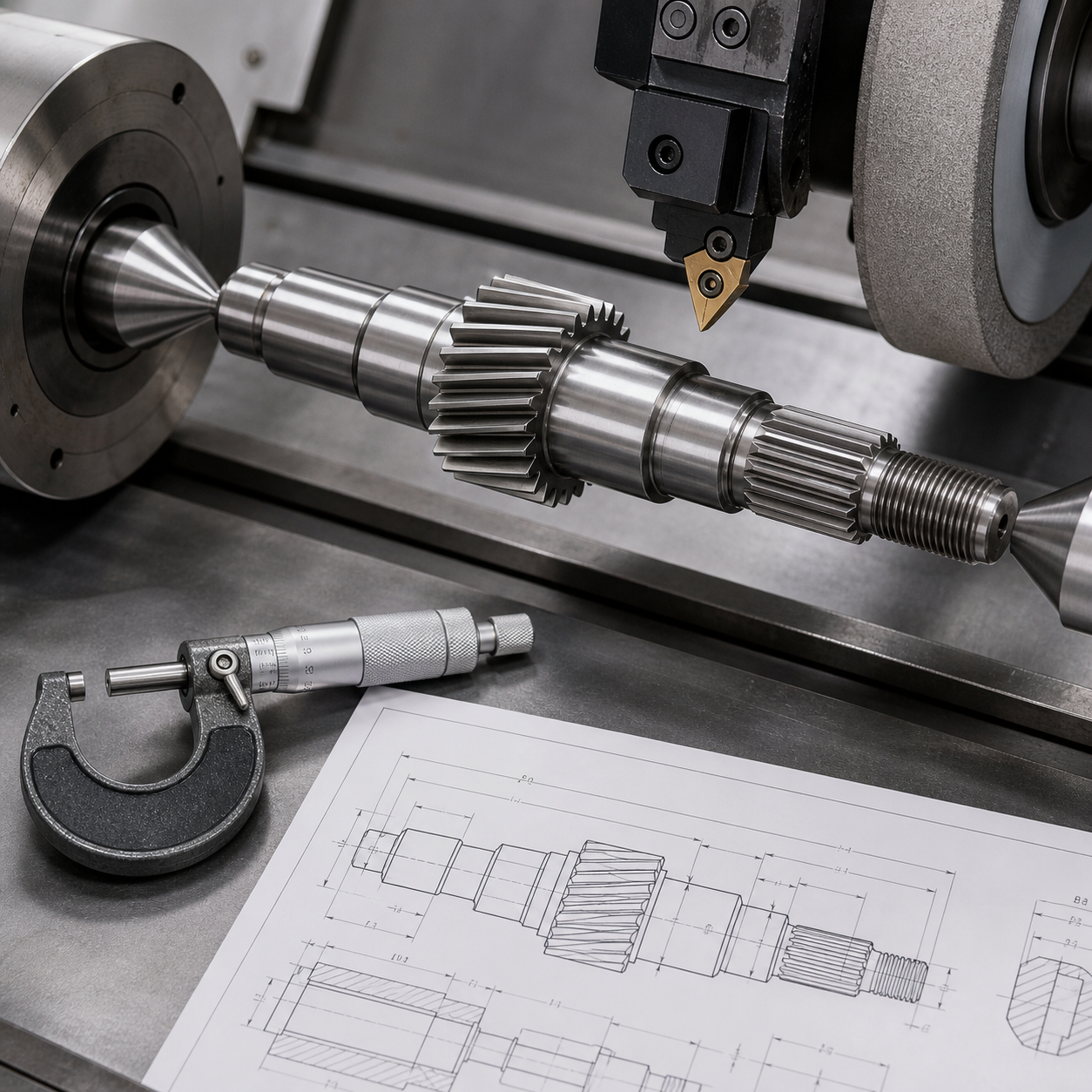
English: Drawing-Based Gear-Shaft Case
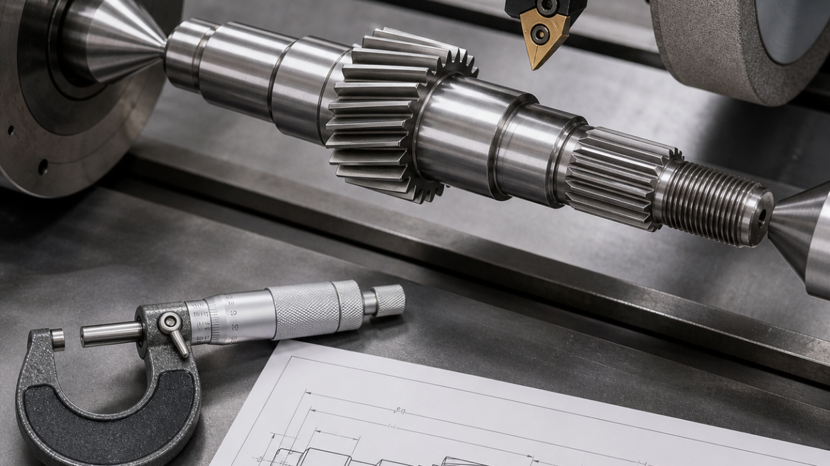
This process case examines a carburized alloy-steel transmission shaft with two bearing journals, a helical gear, an involute spline and an external thread. The illustrative drawing calls for 58-62 HRC at the functional case, 0.008 mm journal roundness, 0.015 mm total runout between bearing seats and a 0.8 micrometre Ra journal finish. Gear quality and case-depth requirements must be defined by the actual customer drawing and heat-treatment specification.
The manufacturing challenge is to preserve a common axis through soft machining, carburizing, hard turning and grinding. Heat treatment changes both size and straightness. If the centers are damaged or no longer represent the functional axis, each later operation can make an individually accurate feature that is nevertheless misaligned with the rest of the shaft.
Datum Chain and Allowance Planning
Create protected 60-degree center holes at both ends before rough turning. Turn all cylindrical features between centers so bearing journals, gear blank and spline blank share one datum axis. Leave heat-treatment allowance according to measured process capability: a typical planning study might begin with 0.25-0.40 mm per diameter on bearing journals and 0.15-0.25 mm on hard-turned shoulders, but the final values must come from distortion data.
Before carburizing, protect threads and surfaces that should not receive the case where the heat-treatment plan requires it. After treatment, clean and inspect the centers; lightly re-lap them only if the process specification permits. Check straightness before removing hard stock. A shaft outside the available correction allowance should be reviewed before grinding rather than forced through the finish sequence.
Tool and Process Selection
| Operation | Suggested tool | Control objective |
|---|---|---|
| Soft turning | Coated carbide CNMG/DNMG system | Create a stable common axis and uniform thermal allowance |
| Gear and spline roughing | Hob or spline mill suited to module | Maintain stock for post-heat-treatment finishing |
| Hard shoulder turning | CBN insert with a small hone | Remove scale and correct axial locations with low force |
| Bearing journals | Aluminum-oxide or CBN grinding wheel | Achieve roundness, size and low surface roughness |
| Thread restoration | Profile grinding or controlled hard thread turning | Recover pitch diameter without damaging the case |
Hard-Turning Starting Window
For a continuous 58-62 HRC cut with a stable CBN insert, an initial speed of 90-150 m/min, feed of 0.05-0.12 mm/rev and depth of cut of 0.10-0.25 mm can be evaluated. Interrupted surfaces require a tougher CBN grade and often a lower speed. Avoid a depth of cut that tracks exactly along the carburized case transition or scale line, because this can promote notch wear.
Hard turning should produce a consistent allowance for grinding rather than attempt to replace grinding everywhere. Bearing seats with demanding roundness, waviness and noise performance remain strong grinding candidates. Shoulders and non-critical diameters may be finished by CBN when the machine, workholding and surface-integrity validation support it.
Grinding and Dressing Strategy
Support the shaft between accurate centers and use a steady rest if the length-to-diameter ratio requires it. Dress the wheel to restore both cutting ability and form. Spark-out should be long enough for size stabilization but not used to hide poor wheel condition. Monitor grinding power, burn indicators and size trend. If the drawing controls the shoulder-to-journal relationship, grind the shoulder and journal in the same datum setup where possible.
Inspection Plan
- Verify case hardness and effective case depth from the approved heat-treatment record.
- Measure center condition and shaft straightness before hard finishing.
- Check journal diameter at multiple axial and angular positions.
- Measure roundness separately from two-point diameter.
- Inspect journal-to-journal runout while the part is supported on its center datum.
- Measure gear lead, profile and pitch on suitable analytical gear equipment.
- Verify spline size and functional fit with the specified gauge.
- Use surface-roughness and burn-detection methods required by the control plan.
A micrometer alone cannot prove roundness or coaxiality. The inspection method must match the geometric characteristic. Trend charts for heat-treatment distortion and grinding correction are especially valuable because they convert allowance selection from guesswork into a controlled production decision.