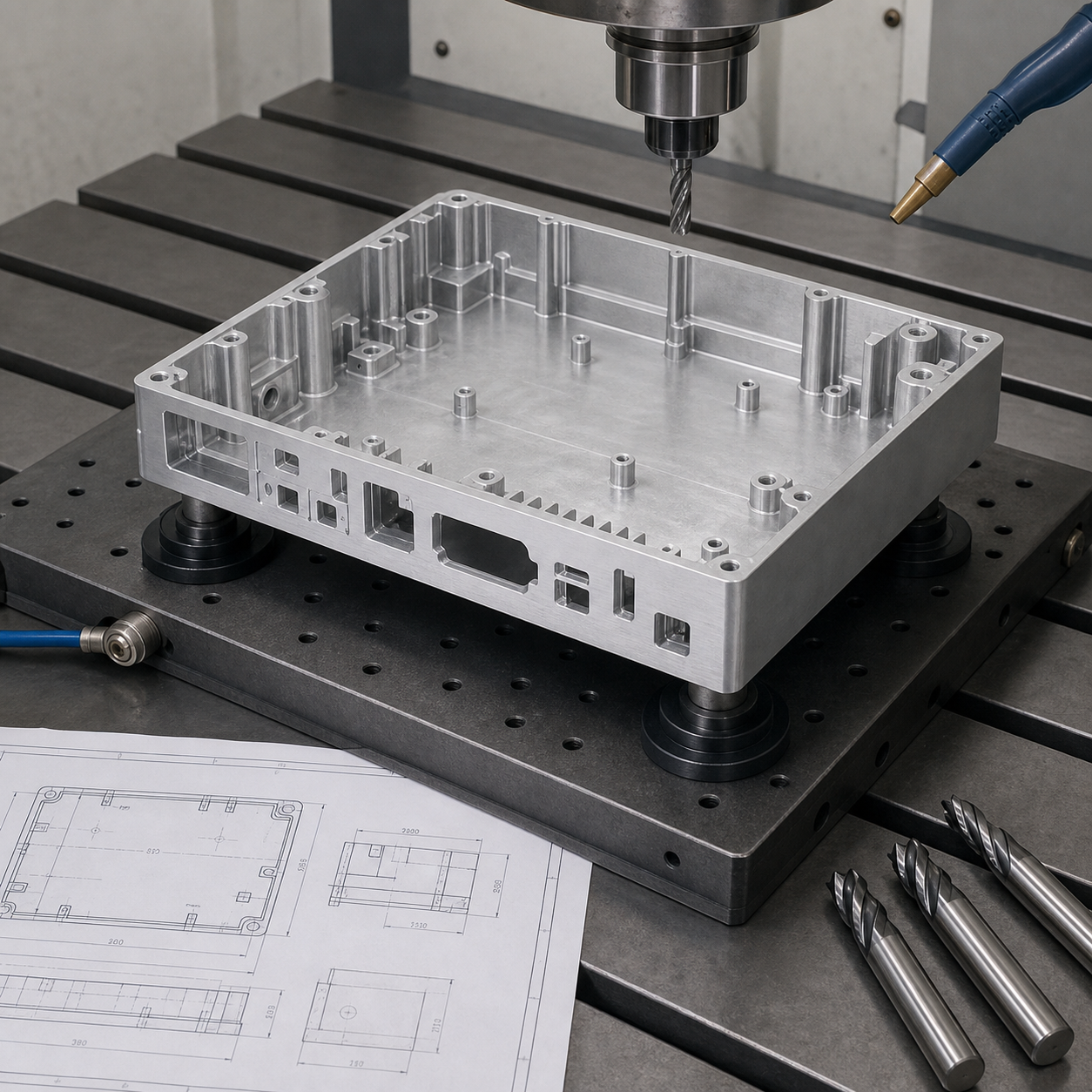
English: Part Drawing and Manufacturing Priorities
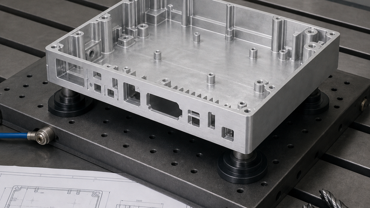
This case study uses an AZ91D magnesium electronics housing measuring approximately 260 x 210 x 55 mm. The casting contains a thin floor, internal ribs, connector windows, threaded bosses and a perimeter sealing land. The drawing specifies 0.08 mm flatness on the sealing land, a 0.10 mm true-position requirement for selected connector holes and a finished wall range of 1.8-2.2 mm.
Magnesium cuts with low force, but that does not make the process casual. Thin sections can vibrate and distort, sharp tools must prevent rubbing, and dry magnesium chips require disciplined collection. Fire prevention is part of process engineering, not a footnote. The machine, extraction system and extinguishing method must be approved for magnesium before production begins.
Fixture and Datum Strategy
Use the as-cast mounting pads for the first setup and machine three datum pads, two locating holes and the sealing land in a controlled sequence. In the second setup, locate from the finished holes and support the broad floor on a dedicated vacuum fixture with distributed rest pads. The vacuum circuit should use zoned seals so open connector windows do not collapse the entire holding system.
Apply mechanical stops in the cutting-force direction and use low-force auxiliary clamps only where the drawing allows. A vacuum gauge connected to the machine interlock should stop the cycle if holding pressure falls. Support placement must follow rib intersections; unsupported floor areas can be pulled into the fixture and spring back after release.
Tooling Plan
| Feature | Suggested tool | Process reason |
|---|---|---|
| Datum pads and sealing land | Single-edge PCD or polished aluminum-geometry face mill | Low cutting force and controlled burr formation |
| Internal pockets | 3-flute polished uncoated carbide end mill | Large flute space and reliable chip evacuation |
| Thin ribs | Sharp reduced-neck carbide end mill | Reach without excessive shank rubbing |
| Connector windows | Small 2- or 3-flute carbide end mill | Low radial load and clean corner interpolation |
| Threads | Carbide thread mill | Lower torque, diameter adjustment and easier recovery |
Starting Parameters and Chip Control
For a 10 mm polished three-flute carbide end mill, an initial cutting-speed range of 400-700 m/min and feed per tooth of 0.05-0.10 mm may be evaluated for stable pocketing. Keep radial engagement moderate and maintain a positive chip thickness. A 6 mm finishing tool may begin near 350-600 m/min with 0.025-0.055 mm per tooth. Reduce engagement before reducing feed so the edge continues to cut instead of rub.
Use a strong, correctly engineered air blast and continuous chip extraction where the facility’s magnesium safety assessment permits it. Do not allow chip piles to accumulate in corners, filters or conveyor pockets. Never use ordinary water or an unsuitable general-purpose extinguisher on burning magnesium. The facility must provide the correct Class D media, written emergency procedure and trained personnel according to local rules.
Machining Sequence
- Confirm alloy, casting condition and facility approval for magnesium machining.
- Machine datum pads and locating holes with conservative support.
- Mount on the zoned vacuum fixture and verify the pressure interlock.
- Rough pockets from the center outward, alternating regions to balance stress.
- Leave 0.3-0.5 mm on the sealing land and critical windows.
- Machine ribs with a constant-engagement path and minimum practical reach.
- Finish the sealing land after major stock removal and a short stabilization period.
- Thread mill bosses, deburr with dedicated tools and perform a complete chip cleanout.
Inspection and Release
Measure the sealing land on a surface plate or CMM after the housing has been released from the vacuum fixture. Inspect connector location from the machined datum holes, not from an inconsistent casting edge. Use a wall-thickness gauge or targeted CMM points where the casting allowance is tight. Record vacuum level and final flatness together; this helps identify whether variation originates in the fixture seal, casting stress or toolpath.