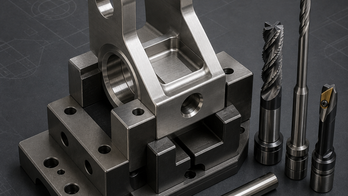
English: Drawing Review and Process Target
This CNC case study examines a 17-4PH stainless steel clevis bracket with two parallel fork arms, a cross hole through both ears, a reamed pivot bore, threaded mounting holes and a flat mounting base. The example drawing calls for 0.03 mm coaxiality between the two fork-ear bores, 0.05 mm perpendicularity from the cross-hole axis to the mounting base and a controlled fork gap after heat treatment. The values are used for process planning; the real customer drawing always controls final acceptance.
The main risk is that the two fork ears behave like flexible cantilevers after the center slot is opened. If the shop roughs the slot too early or finishes one ear without supporting the other, the cross hole can measure acceptable in the machine and move after unclamping. The process therefore needs a clear datum chain, staged material removal and support during the final bore operation.
Fixture and Datum Strategy
Machine the mounting base and two locating holes before separating the fork arms. These features become the repeatable datum set for later operations. Rough the outside profile while the blank still has bridge stock between the ears, then open the fork slot in stages. A removable spacer or soft expanding support inside the fork gap helps control deflection during finishing.
For the cross hole, use one setup whenever possible. Drill undersize, interpolate or bore the first ear, continue through the spacer and finish the second ear from the same coordinate system. If the machine cannot reach both sides cleanly, a qualified flip fixture and probing routine must prove that the second setup repeats the datum axis.
Tooling Plan
| Feature | Suggested tool | Reason |
|---|---|---|
| Base and profile roughing | Variable-helix carbide end mill with tough coating | Reduces chatter in precipitation-hardened stainless steel |
| Fork slot roughing | High-performance carbide end mill, constant engagement path | Balances force and protects the thin ears |
| Fork wall finishing | Sharp carbide end mill with small corner radius | Controls wall finish without pushing the ears away |
| Cross hole | Carbide drill, boring tool or reamer depending on tolerance | Maintains diameter, coaxiality and surface condition |
| Deburring | Back-chamfer tool or programmed ball/chamfer mill | Removes hidden burrs between the fork ears |
Starting Cutting Parameters
For 17-4PH in H1025-H1150 condition, a 10 mm carbide end mill may start around 90-140 m/min, 0.035-0.070 mm per tooth and 8-15 percent radial engagement for trochoidal roughing. Finishing the fork walls can begin near 80-120 m/min with 0.025-0.050 mm per tooth and a light radial pass. Cross-hole drilling and reaming should follow the tool supplier’s grade data, with coolant aimed directly at chip evacuation.
Operation Sequence and Inspection
- Verify material condition, heat-treatment state and stock allowance.
- Machine the mounting base, locating holes and rough outside profile.
- Rough the fork slot while leaving bridge stock or support in place.
- Semi-finish fork walls equally on both sides to balance stress.
- Install a controlled spacer and finish the fork gap.
- Machine the cross hole from one datum system and deburr both exits.
- Inspect fork gap, bore size, coaxiality, perpendicularity and base flatness after unclamping.
The SEO theme is 17-4PH clevis bracket CNC machining, cross-hole alignment, fork finishing and carbide tool selection. These terms describe the real process problem, so they are used naturally instead of repeated as keyword stuffing.


