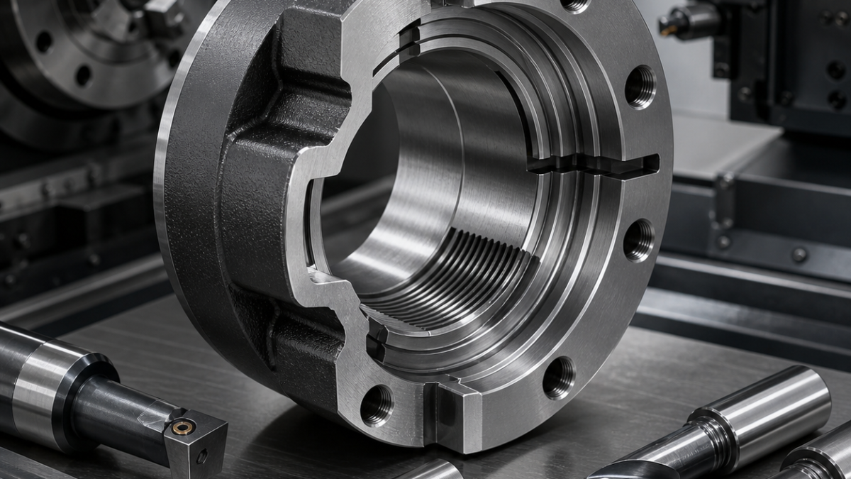
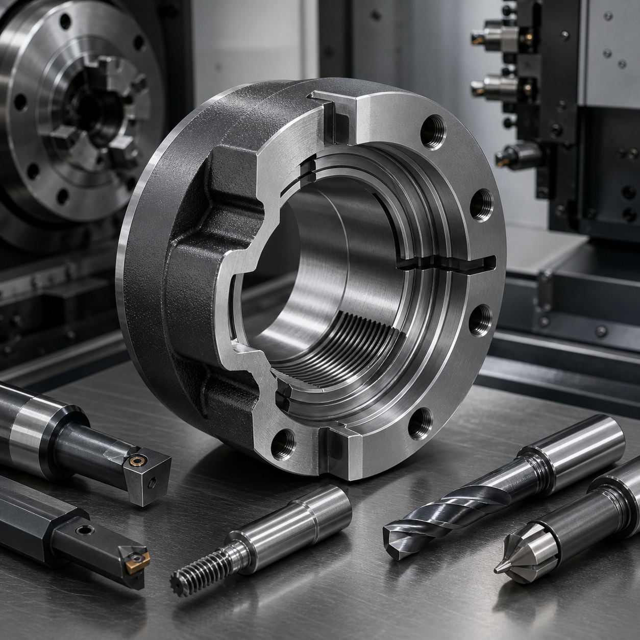
An AISI 4140 hydraulic cylinder end cap machining plan must coordinate a stepped bore, seal and backup-ring grooves, internal thread, flange bolt circle and sealing face. The most important decision is datum continuity: features that seal and guide the rod or piston should be produced and inspected from the same axis whenever the machine configuration permits.
Drawing Review and Material Condition
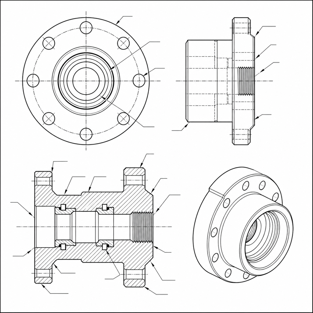
Confirm whether 4140 is supplied normalized, prehardened or quenched and tempered. Hardness changes insert grade, edge preparation and expected tool life. Identify datum face A, bore axis B, flange bolt-circle position, seal-groove width/depth, corner radii, surface finish and thread class. Seal grooves must match the actual seal and backup-ring specification; a generic groove chart must not override the released design.
Workholding and Datum Strategy
Use soft jaws or a controlled chucking diameter for the first turning setup. Face and rough the OD, then create the bore datum. Reverse on a finished pilot or soft jaws and finish the mounting face, bore, grooves and thread in one setup where possible. Control clamping pressure so the round part does not spring after release. For the bolt circle, locate from the finished bore with an expanding mandrel or a probed fixture.
Tooling Matrix
| Feature | Preferred tool | Quality control |
|---|---|---|
| Face and OD | Positive-rake carbide turning insert | Stable datum, burr direction and surface finish |
| Stepped bore | Rough boring bar plus fine boring bar | Measure semi-finish size and compensate |
| Seal grooves | Ground full-profile or precision grooving insert | Width, depth, corner radius and tool deflection |
| Internal thread | Threading bar or thread mill | Pitch diameter, effective length and runout relief |
| Bolt circle | Spot drill, carbide drill and chamfer mill | True position to bore datum |
Recommended Process Sequence
- Verify hardness and stock allowance; face and rough-turn the first side.
- Rough the central bore, leaving uniform stock for heat and stress stabilization.
- Reverse on controlled soft jaws or a pilot; probe or indicate the datum axis.
- Finish the mounting face and fine-bore the guiding diameters.
- Cut seal and backup-ring grooves with a qualified insert and measured tool offset.
- Machine the internal thread and verify functional engagement.
- Transfer to the machining center or live-tool station for the bolt circle and auxiliary ports.
- Deburr without rolling material into the grooves; clean, inspect and pressure-test the assembly as specified.
Starting Data and Tool-Life Control
For stable turning of 4140 around 28-32 HRC, coated carbide often starts in a broad 100-180 m/min region. Grooving and threading generally require lower values and close attention to overhang. Treat these figures only as a trial window: use the insert supplier’s grade-specific recommendation and verify hardness, spindle power, coolant and rigidity. Track groove tools by parts per edge and inspect the corner radius, because a worn grooving insert can pass width measurement while damaging the seal contact surface.
Failure Modes and Countermeasures
- Bore taper: shorten bar overhang, increase bar diameter and use a spring-pass study only after correcting rigidity.
- Groove chatter: minimize blade projection, verify center height and cut with controlled radial engagement.
- Thread bell-mouth: stabilize entry and exit motion and provide the correct relief geometry.
- Released-part ovality: reduce chuck pressure, use bored soft jaws and measure after unclamping.
- Seal damage during assembly: control edge breaks and inspect groove corners rather than applying a large general chamfer.
Inspection Plan
Inspect bore diameter, taper, roundness and coaxiality to the mounting face. Use a calibrated groove gauge, optical comparator or CMM strategy for seal-groove width, depth and radii. Verify the internal thread with the specified gauge and functional mating part when required. Check bolt-circle true position from the bore datum. Record surface finish on sealing and guiding diameters, and apply magnetic-particle inspection or hardness verification when the drawing calls for it.
中文工艺方案
4140 液压缸端盖的关键是内孔轴线、密封槽、内螺纹与安装端面的统一基准。先确认材料是正火、预硬还是调质状态,因为硬度会直接影响刀片牌号、切削速度和刀具寿命。第一装夹建立端面和内孔基准,翻面后尽量在同一装夹内完成安装面、精镗孔、密封槽和内螺纹。
密封槽应采用经过确认的精密槽刀,重点控制槽宽、槽深、圆角和刀具挠曲。不能只检查槽宽;刀尖圆角磨损可能不会立即改变宽度,却会破坏密封接触区域。夹紧力过大还会造成松夹后圆度变化,因此软爪必须按实际夹持直径加工并验证。
最终检查包括孔径、锥度、圆度、同轴度、端面跳动、槽形、螺纹有效长度和螺栓孔位置度。若图纸要求,还应进行硬度、磁粉或压力测试。
Résumé français
Le couvercle de vérin en acier 4140 doit conserver un axe commun entre l’alésage, les gorges d’étanchéité, le filetage intérieur et la face de montage. La dureté réelle du matériau est vérifiée avant de choisir la nuance de plaquette et les conditions de coupe.
Une barre d’alésage rigide prépare les diamètres, puis un outil de gorge rectifié réalise les logements de joint et de bague anti-extrusion. Le serrage en mors doux doit éviter l’ovalisation après desserrage. Le contrôle final couvre la conicité, la circularité, la géométrie des gorges, le filetage et la position du cercle de trous.
Русское резюме
В крышке гидроцилиндра из стали 4140 отверстие, уплотнительные канавки, внутренняя резьба и монтажный торец должны сохранять общую ось. Перед обработкой проверяют состояние термообработки и твердость, так как они определяют марку пластины и режимы резания.
Отверстие чистят жесткой расточной оправкой, а канавки выполняют профильной пластиной с контролем ширины, глубины и радиуса. Мягкие кулачки и ограниченное усилие зажима уменьшают овальность после освобождения детали. Контролируют конусность, круглость, канавки, резьбу и позицию отверстий фланца.
FAQ
Should the seal grooves and bore be finished in one setup?
Yes, whenever practical. A common rotational datum reduces accumulated coaxiality error and simplifies functional inspection.
Why verify hardness before selecting cutting data?
4140 covers several heat-treatment conditions. A speed suitable for normalized stock may cause rapid wear or instability in prehardened material.
Related CNC Cases
Compare the bearing-housing fine-boring case and the CNC thread-milling guide.


