This is a hypothetical drawing-based technical study, not a claim about a customer project or verified production result.
English: Titanium Alloy CNC Milling Tool Selection for Heat Control and Carbide End Mill Life
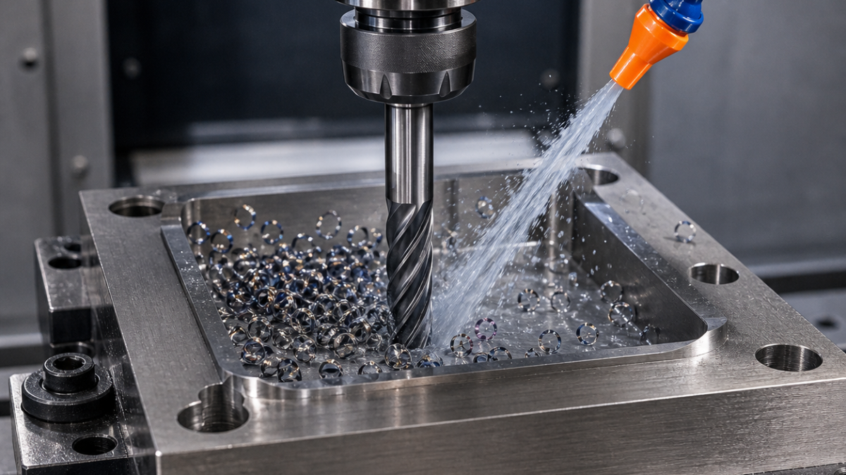
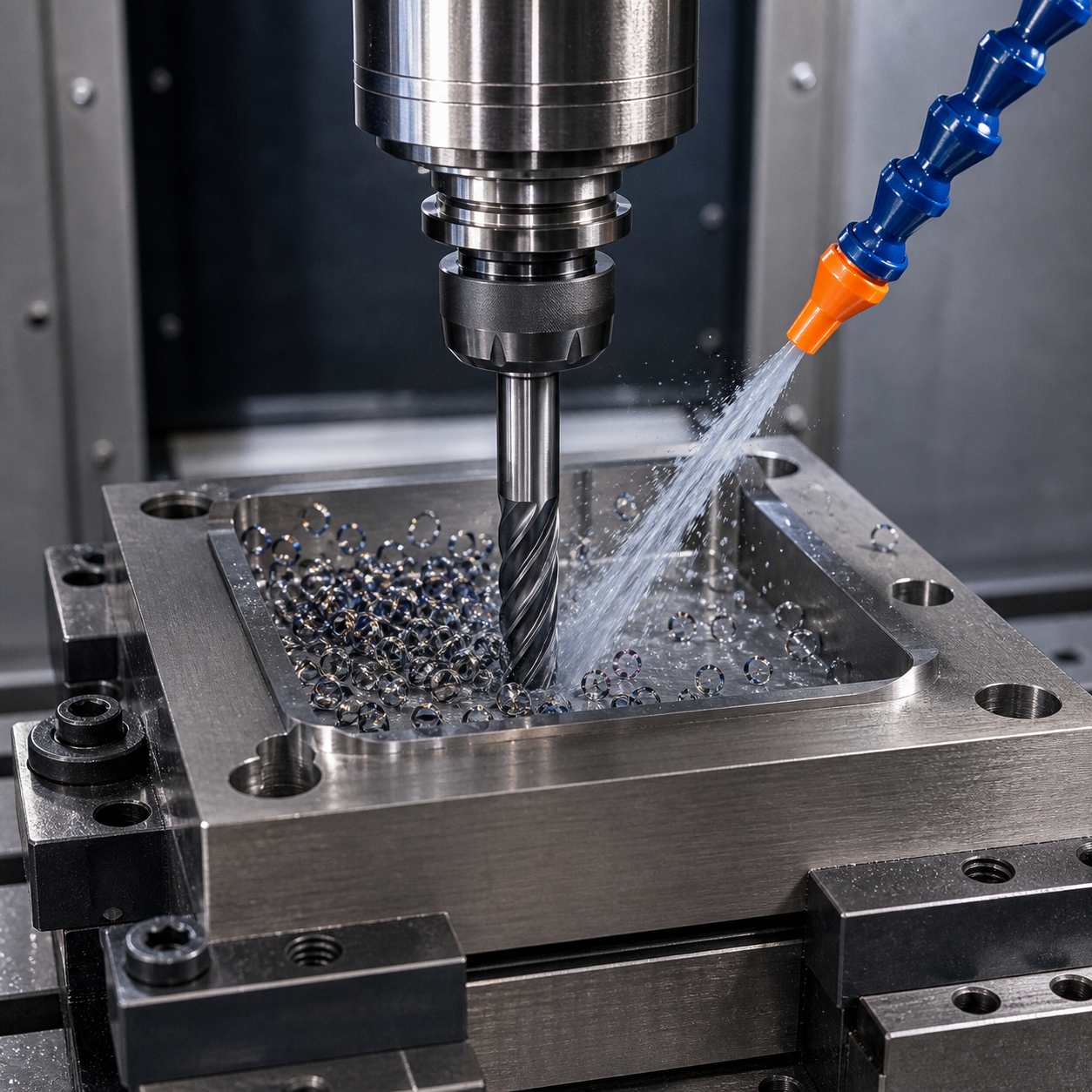
Titanium heat control is mainly a contact-time and chip-evacuation decision. In a hypothetical Ti-6Al-4V bracket, the drawing links a 55 mm deep pocket, 1.2 mm ribs, R3 internal corners, H7 holes and an angled mounting face. A single “titanium end mill” cannot serve all five features without excessive reach or heat.
Give each feature its own edge and reach
Rough the open pocket with a 12 mm four-flute variable-helix micrograin carbide radius end mill, sharp but lightly honed, with a heat-resistant PVD coating and through-spindle coolant. Use an 8 mm relieved-neck four-flute tool for residual corners, a 6 mm five-flute finisher for supported walls, a ball-nose tool only for the blended surface, and short through-coolant carbide drills followed by boring or reaming only where position is already secure. A six-flute rougher is rejected because it traps hot chips; one extra-long tool is rejected because it sacrifices stiffness everywhere.
Plan heat out of the toolpath
Clamp the billet on a qualified base with a wide support window, rough both sides symmetrically, and leave ribs connected by sacrificial tabs. Use low radial engagement, adequate axial depth and a smooth adaptive path; roll into corners and prohibit stationary dwell. Recutting titanium chips is especially damaging, so coolant and air must clear the next engagement. Semi-finish datums before opening thin ribs, then finish walls in alternating levels with a constant stock allowance.
Protect the edge with measurable limits
Do not respond to heat by starving feed: rubbing concentrates heat in the tool. Maintain chip thickness through arcs, reduce engagement before speed, and keep the holder short and low-runout. Watch corner chipping, flank-wear width, spindle load and the color/shape of chips. Retire the rougher at the agreed wear limit or a sustained load rise. For deep holes, monitor coolant flow and chip return; a blind peck cycle without evacuation evidence only repeats heat at the same band.
Inspection after stress release
Probe the base, hole pattern and remaining wall stock between setups. Inspect H7 diameter, position and cylindricity only after the final datum is established. Measure rib profile after tab removal, surface texture in the functional direction, and internal corners for smeared material or burrs. Recheck flatness after unclamping because titanium residual stress can convert an in-fixture result into a released error.
| Drawing feature | Carbide tool and holder | Why / rejection |
|---|---|---|
| Deep pocket / 深型腔 | 12 mm, 4-flute variable-helix radius carbide; short shrink-fit | Chip space and stiffness; six flutes rejected |
| R3 residual corner / 内圆角 | 8 mm, 4-flute relieved-neck carbide; hydraulic | Reach only where needed |
| Thin rib / 薄筋 | 6 mm, 5-flute sharp finisher; low-runout holder | Lower force with supported alternating levels |
| H7 hole / 精密孔 | Short through-coolant carbide drill plus boring/reaming | Position first; long drill rejected |
Related technical cases: Ti-6Al-4V bracket case; titanium bone-plate machining; titanium wrist-clamp tooling.
FAQ
Why does stainless/titanium fail after a pause? The edge rubs or re-enters a heat-affected/work-hardened band instead of taking a stable chip.
How should tool life be ended? Use a defined wear, load, size-correction or surface trend, before unpredictable chipping.


