English: Ti-5553 Landing Gear Axle CNC Tooling Case: Bearing Journals and Cross-Hole Breakout
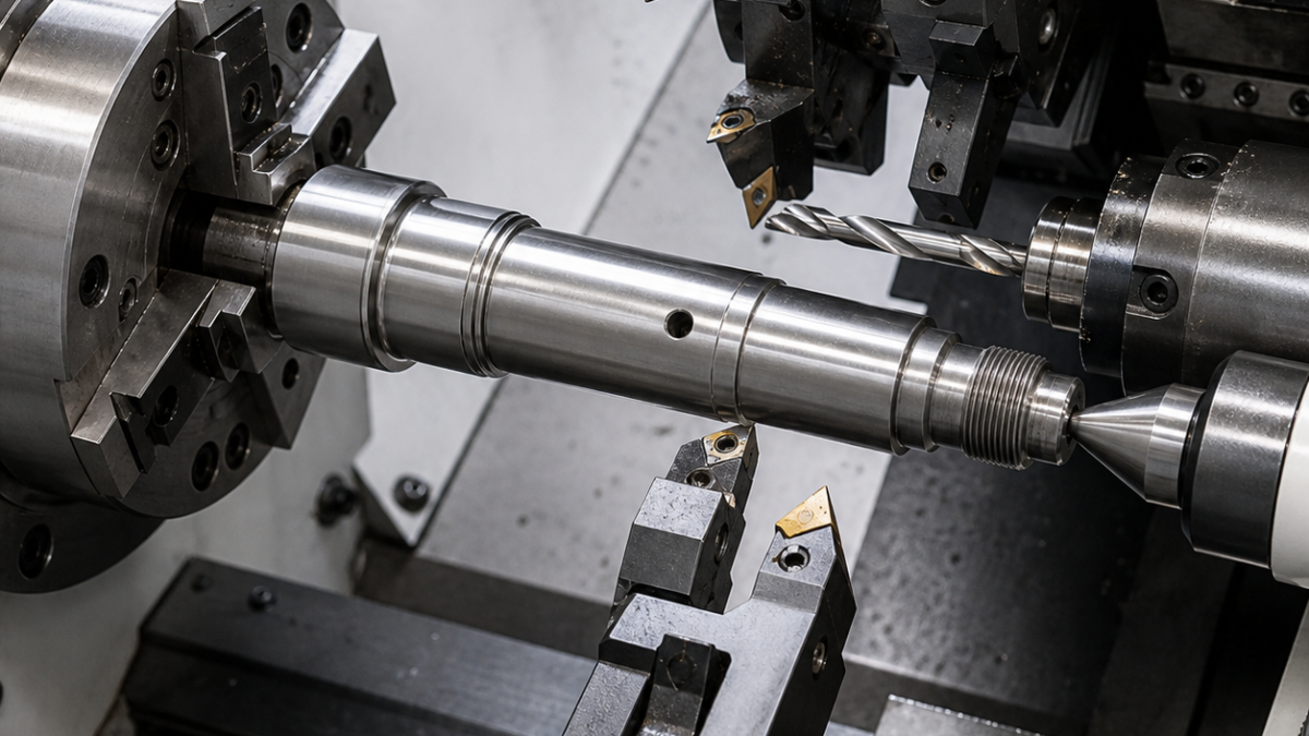
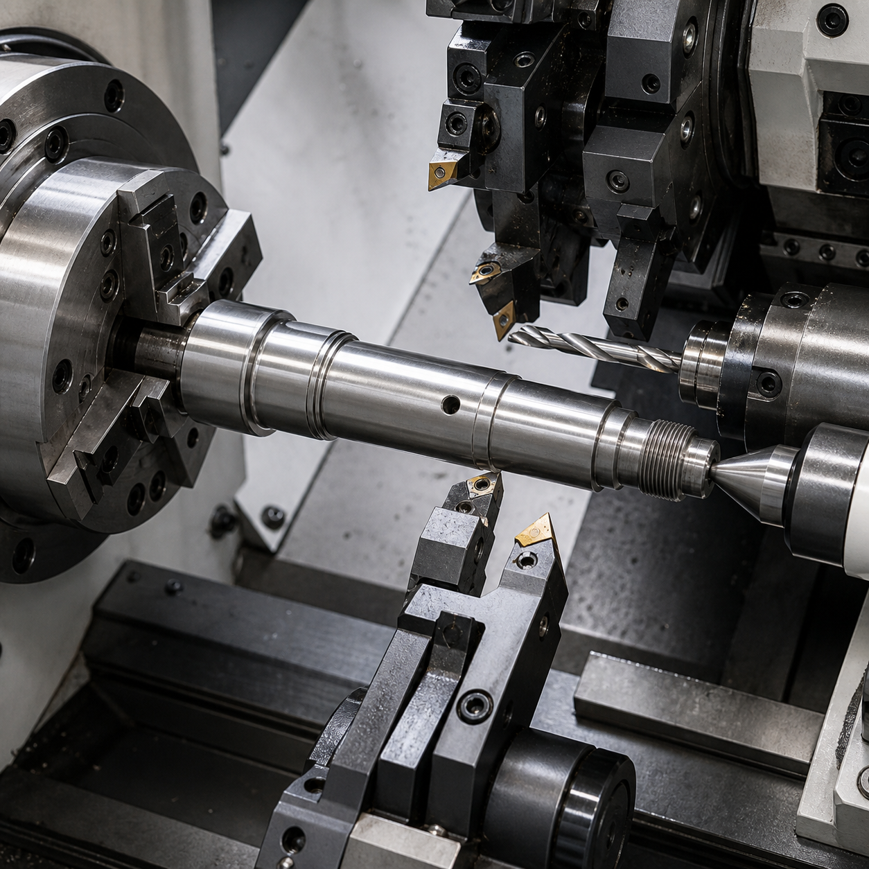
The tooling answer for a Ti-5553 landing-gear axle is a controlled turn–drill handoff: a tough coated insert removes the forged skin, a fresh positive finishing insert establishes both bearing journals from one axis, a guided carbide drill creates the deep lubrication passage, and a back-chamfer tool removes the cross-hole feather without touching the finished journal. This hypothetical drawing case explains why those tools are separated instead of asking one general-purpose insert to do everything.
Tolerance flow from the axle axis
Journal J1 is datum A; the left shoulder is datum B and the Ø6 lubrication breakout clocks datum C. J1 is Ø68 k5, J2 is Ø62 k5, their common-axis total runout is 0.012 mm, and the 1:12 tapered seat is limited to 0.015 mm runout from A. Two 2.5 mm relief grooves protect bearing corners, the axial oil bore is Ø10 × 185 mm, and the M48 × 1.5 thread must gauge without rolling a burr toward J2. Journal finish is Ra 0.4 µm. The forging may carry local alpha-case and uneven scale, so skin removal and precision finishing use different edge preparations.
Drawing feature to carbide tool map
| Feature | Selected tool, geometry and holder | Decision and rejected alternative |
|---|---|---|
| Forged skin and stock balance | CNMG 120408, tough S-grade micrograin carbide, PVD TiAlN, 0.05 mm edge hone, rigid lever-lock holder with high-pressure coolant | The reinforced edge survives scale interruptions. A polished uncoated finishing insert is too fragile for the first contact. |
| J1/J2 bearing journals | Ground VBMT 160404 positive insert, fine-grain carbide with thin PVD coating, sharp rake, R0.4, precision modular holder | Low radial force and controlled nose radius support Ra 0.4. A wiper geometry is rejected because small alignment error can widen the contact band. |
| 1:12 tapered seat | Fresh copy of the VBMT finishing edge, calibrated tool station, minimum overhang | One edge family keeps size and surface response consistent. A form tool would load the taper across its full width. |
| 2.5 mm relief grooves | 2.0 mm PVD-carbide grooving insert followed by two compensated side shifts, through-tool coolant | Side shifts control both corners and avoid a fragile 2.5 mm form blade rubbing the titanium. |
| Ø10 × 185 mm oil bore | Single-lip solid-carbide gun drill, 30×D qualified length, TiAlN tip, guide bush and filtered high-pressure oil | The guide bush controls drift. A standard twist drill at this depth would wander and recut chips. |
| Ø6 cross passage | Ø5.8 stub carbide drill, 140° point, four-margin geometry, hydraulic chuck; Ø3 reverse-cut carbide back-chamfer tool | The drill controls breakout, then the reverse cutter removes the internal feather. Hand scraping through the bore is not repeatable. |
| M48 × 1.5 thread | Full-profile PVD-carbide threading insert, sharp positive chip former, rigid external holder | Controls crest and root in few passes. A partial-profile insert leaves crest burr dependent on blank diameter. |
Machining sequence, support and heat control
The forging is first probed at both journal envelopes, then rough-turned between a chuck and live center while a programmable steady supports the center span. Equal stock is left on J1 and J2, and the component rests before a second center reference is cut. In the finishing setup, J1, J2 and the taper are completed without releasing the axial stop. The final journal pass uses constant surface speed, no dwell and a documented insert edge; a spring pass is permitted only after an air-gauge trend proves it cuts rather than rubs.
The gun drill enters from B through a prepared pilot. Flow, pressure and chip signature are monitored before the tool reaches the cross-hole zone. C-axis drilling of Ø6 occurs while a sacrificial support pin occupies the axial passage; the reverse chamfer then cuts only the internal edge. Titanium’s low thermal conductivity makes flank wear, notch wear at shoulders and blue compacted chips the principal tool-life signals. A rising load slope triggers replacement—feed is not reduced until the edge begins polishing.
Inspection and practical search questions
A roundness instrument measures J1 and J2 at three axial stations and reconstructs their common axis. Air gauges verify k5 sizes after temperature equalization; a CMM checks the taper, shoulders, groove location and cross-hole clocking. Borescope inspection confirms a continuous internal break with no loose feather. Oil-flow testing supplements, but does not replace, the measured bore path. Thread acceptance uses a clean ring gauge after the journal surfaces are protected.
Which carbide insert should finish Ti-5553 bearing journals?
Use a ground positive fine-grain insert with a sharp rake, small nose radius and stable PVD coating; here VBMT R0.4 limits radial force while holding Ra 0.4 µm.
How is the burr removed where a cross hole meets a deep oil bore?
Support the breakout during drilling, then use a small reverse-cut carbide back-chamfer tool viewed through a borescope.
Why not use a conventional twist drill for the 185 mm oil passage?
A guided single-lip carbide drill provides controlled straightness and continuous high-pressure chip evacuation at this depth.
Compare the thermal-cutting choices in Ti-6Al-4V thin-section machining and the axis-to-hole handoff in a pressure-probe tooling case.
中文: Ti-5553起落架轴配刀:轴承外圆、深油孔与交叉孔去毛刺
Ti-5553起落架轴的配刀核心是车削与深孔工序分工:韧性涂层刀片先去锻造皮,锋利正角刀片在同一轴线完成两处轴承外圆,导向硬质合金深孔钻加工润滑通道,反向倒角刀再从内侧去除交叉孔翻边。这样可避免通用刀片在粗皮、精外圆和孔口三种完全不同的负载下折中。
图纸公差链
J1为A基准,左肩为B,Ø6润滑孔定义C方向。J1为Ø68 k5,J2为Ø62 k5,共轴线总跳动0.012 mm;1:12锥面相对A跳动0.015 mm。轴向油孔Ø10、深185 mm,两条退刀槽宽2.5 mm,M48×1.5螺纹不得把毛刺卷向J2,轴承面Ra 0.4 µm。锻件局部氧化皮和硬化表层决定了开粗刃口必须比精车刃口更强韧。
图纸特征—刀具配刀表
| 特征 | 刀具、几何与刀柄 | 选择及排除理由 |
|---|---|---|
| 锻造皮开粗 | CNMG 120408,S类韧性细晶硬质合金,PVD TiAlN,0.05 mm刃口强化,高压内冷刚性刀杆 | 能承受断续氧化皮;抛光无涂层精刀首次接触易崩。 |
| J1/J2轴承面 | 精磨VBMT 160404正角细晶刀片,薄PVD涂层,R0.4,模块化精密刀杆 | 径向力小;修光刃在微小偏斜时会扩大接触带。 |
| 1:12锥面 | 同规格新VBMT刃口,标定刀位,最短悬伸 | 与外圆保持一致的磨损响应;大成形刀会全宽受力。 |
| 2.5 mm退刀槽 | 2.0 mm PVD硬质合金槽刀,左右补偿侧移,刀内冷却 | 分别控制两侧,避免2.5 mm宽刀整体摩擦。 |
| Ø10×185油孔 | 单刃整体硬质合金枪钻,30D级,TiAlN刀尖,导套和过滤高压油 | 导套控制偏斜;普通麻花钻会走偏并重复切屑。 |
| Ø6交叉孔 | Ø5.8短型四刃带140°硬质合金钻+Ø3反向切削倒角刀,液压夹头 | 先控制出口,再从内侧切掉薄毛边;手工伸入油孔不可重复。 |
| M48×1.5 | 全牙型PVD硬质合金螺纹刀片,锋利正角断屑槽 | 同时控制牙顶牙底;部分牙型刀过分依赖毛坯直径。 |
工序、支承与刀寿风险
先探测两段外圆余量,用卡盘、活顶尖和可编程中心架粗车,J1、J2留等量精余量;静置后重修中心基准。精车装夹中不松开轴向止挡,连续完成两外圆与锥面。精刀采用恒线速、不停顿的单向走刀;只有气动量仪趋势证明弹簧刀确实切削时才允许重复走刀。
枪钻从B端的精确导向孔进入,实时监控压力、流量和切屑形态。C轴钻Ø6时在轴向孔内放置牺牲支承销,随后用反向倒角刀只切内口。后刀面磨损、台阶处沟槽磨损和发蓝压实屑是换刀信号;负载斜率上升时直接换刃,不通过降进给继续摩擦。
检验与常见问题
圆度仪在J1、J2各三个轴向位置测量并重建共轴线;温度稳定后用气动量仪确认k5尺寸,三坐标测锥面、肩位、槽位和交叉孔方向。内窥镜确认交叉处倒钝连续且无游离毛边,油流测试仅作功能补充,不能替代孔路几何数据。
Ti-5553轴承外圆用什么精车刀片?
选锋利正角、细晶、薄PVD涂层和小刀尖圆弧的精磨刀片,本例VBMT R0.4兼顾Ra与低径向力。
深油孔与交叉孔处怎样去毛刺?
钻削时支承出口,再用Ø3反向硬质合金倒角刀从油孔内侧切除毛边并内窥检查。
为何不用普通麻花钻加工185 mm孔?
导向单刃枪钻能在深径比条件下同时控制直线度和高压排屑。
Français: Essieu Ti-5553 : outils pour portées et perçage transversal
Sur cet essieu Ti-5553, l’ébauche de peau, la finition des portées et l’intersection des conduits exigent trois familles d’outils. Une plaquette tenace ouvre la forge, une géométrie positive termine les deux portées sur le même axe, puis un foret carbure guidé et un outil à chanfreiner en retour maîtrisent le conduit profond.
Chaîne de tolérances
J1 définit A, l’épaulement B et le trou Ø6 l’orientation C. J1 vaut Ø68 k5, J2 Ø62 k5, avec battement commun 0,012 mm. Le cône 1:12 tient 0,015 mm; le canal Ø10 atteint 185 mm et les portées demandent Ra 0,4 µm.
Tableau fonction–outil
| Fonction | Outil | Motif |
|---|---|---|
| Peau forgée | CNMG 120408 carbure S tenace, TiAlN PVD, honage 0,05 mm, arrosage haute pression | Résiste aux interruptions; une arête polie est trop fragile. |
| Portées J1/J2 | VBMT 160404 rectifiée, positive, carbure fin PVD, R0,4 | Faible effort radial; une racleuse amplifie un défaut d’alignement. |
| Cône | VBMT neuve identique, porte-outil court | Réponse d’usure cohérente, contrairement à un outil de forme large. |
| Gorges 2,5 mm | Lame carbure PVD 2,0 mm avec deux décalages | Contrôle séparé des flancs. |
| Canal Ø10 | Foret une lèvre carbure, 30D, TiAlN, canon de guidage | Rectitude et évacuation filtrée. |
| Trou Ø6 | Foret carbure Ø5,8 à 140° puis outil retour Ø3 | Élimine la bavure interne sans grattage. |
| Filetage | Plaquette carbure PVD à profil complet | Maîtrise sommet et fond. |
Processus, durée de vie et contrôle
La pièce est ébauchée entre mandrin, pointe et lunette, puis stabilisée. J1, J2 et le cône sont finis sans libérer la butée. Le foret profond part d’un pilote; une broche sacrificielle soutient la sortie du trou transversal. Usure en dépouille, entaille et copeaux bleuis déclenchent le remplacement.
Le rondimètre reconstruit l’axe commun; les jauges pneumatiques contrôlent k5 et la MMT le cône, les gorges et C. Une caméra vérifie le chanfrein interne.
Quelle plaquette de finition?
Une VBMT positive fine, R0,4, avec revêtement PVD mince.
Comment casser la bavure interne?
Avec un outil carbure de retour Ø3 après soutien du débouché.
Pourquoi un foret une lèvre?
Pour guider 185 mm et évacuer les copeaux sous pression.
Voir la gestion thermique du titane et les trous radiaux d’une sonde.
Русский: Ось Ti-5553: шейки и пересечение масляных каналов
Для оси Ti-5553 нужны разные кромки: прочная пластина снимает поковочную корку, позитивная чистовая пластина формирует обе шейки с одной оси, а направляемое карбидное сверло и обратная фасочная фреза обрабатывают глубокий канал и его пересечение.
Допуски чертежа
J1 задаёт A, торец B, отверстие Ø6 — C. J1 имеет Ø68 k5, J2 Ø62 k5, общее биение 0,012 мм. Конус 1:12 держит 0,015 мм, канал Ø10 идёт на 185 мм, шероховатость шеек Ra 0,4 мкм.
Таблица элемент–инструмент
| Элемент | Инструмент | Решение |
|---|---|---|
| Корка | CNMG 120408, прочный S-карбид, PVD TiAlN, фаска 0,05 мм, высокое давление | Выдерживает удар; полированная кромка хрупка. |
| J1/J2 | Шлифованная VBMT 160404, позитивная, тонкий PVD, R0,4 | Малая радиальная сила. |
| Конус | Новая VBMT той же серии, короткий держатель | Нет полной нагрузки формового резца. |
| Канавки | PVD-карбид 2,0 мм с боковыми смещениями | Независимые стороны. |
| Канал Ø10 | Однокромочное карбидное сверло 30D, TiAlN, кондуктор | Прямолинейность и вывод стружки. |
| Ø6 | Карбид Ø5,8, 140°, затем обратная фасочная Ø3 | Убирает внутренний заусенец. |
| Резьба | Полнопрофильная PVD-карбидная пластина | Контроль вершины и впадины. |
Маршрут и контроль
Черновая обработка идёт между патроном, центром и люнетом. После выдержки J1, J2 и конус заканчивают без разжима. Глубокое сверло входит по пилоту; выход поперечного отверстия поддерживает жертвенный штифт. Износ по задней поверхности, канавка и синяя стружка задают смену.
Кругломер строит общую ось, пневмокалибры проверяют k5, КИМ — конус и C, бороскоп — внутреннюю фаску.
Какая пластина для шеек?
Позитивная VBMT R0,4 из мелкого карбида с тонким PVD.
Как убрать внутренний заусенец?
Обратной карбидной фасочной фрезой Ø3.
Почему однокромочное сверло?
Оно направляет проход 185 мм и выводит стружку.


