English: Hastelloy C-276 Valve Plate CNC Tool Selection for Spiral Purge Slot and Knife-Edge Seat
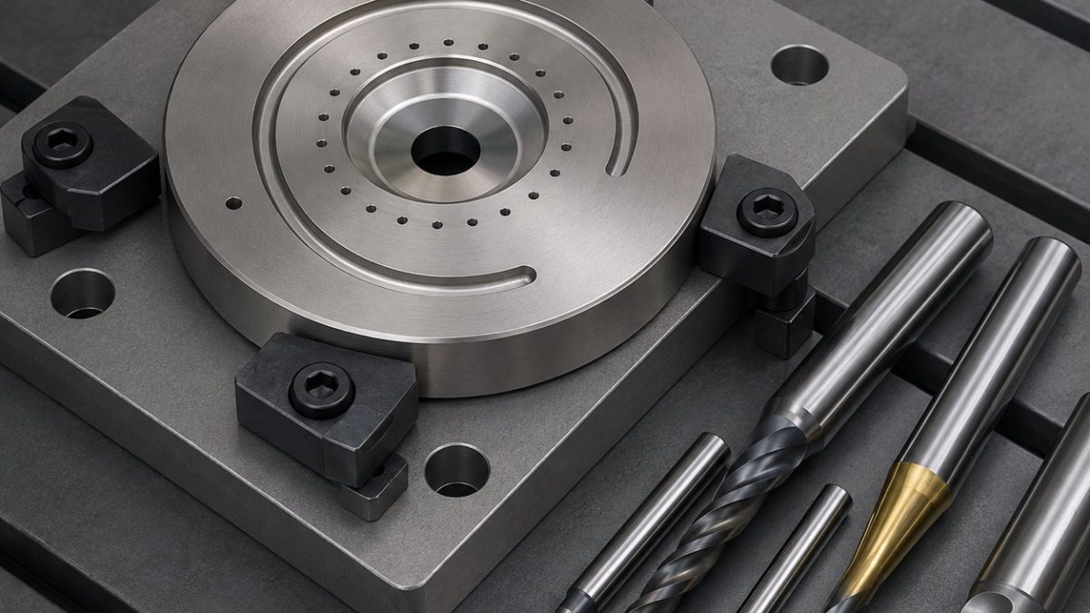
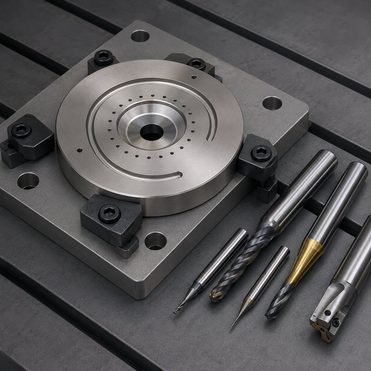
This case answers a specific search problem: how to choose carbide tools for a Hastelloy C-276 diaphragm pump valve plate when the drawing combines a leak-sensitive knife-edge seat, a shallow spiral purge slot and many tiny bleed holes. The workable plan is not to “mill the plate then deburr it”; it is to protect the seat datum first, keep every tool cutting under load, and reserve a controlled finishing pass for the features that touch fluid sealing.
Drawing reading and datum logic
The hypothetical drawing uses the rear face as datum A, the centre bore as datum B and one dowel notch as clocking datum C. The knife edge controls leakage, the spiral slot controls purge flow, and the bleed holes must break into the slot without a torn exit. Similar nickel-alloy behaviour is discussed in AXKXA’s nickel-alloy tool-life control, but this plate is flatter, thinner and more sensitive to local rubbing.
Feature-to-tool selection table
| Drawing feature | Selected tool | Why this tool, and what is rejected |
|---|---|---|
| Scale skin and OD datum pad | Positive 45° lead face mill, PVD AlTiN, honed carbide inserts | Reduces entry shock; a neutral rake rougher is rejected because it rubs before cutting C-276. |
| Knife-edge conical seat | Small-diameter solid-carbide tapered finisher, polished flute, light hone | Maintains seat angle with low pressure; a form insert is rejected because minimum chip load is too high near the tip. |
| Spiral purge slot | Ø2.0 mm 4-flute variable-helix carbide end mill, AlTiN, shrink-fit holder | Stable enough for full spiral interpolation; a 2-flute aluminium cutter is rejected for edge chipping and short life. |
| Ø0.8 mm bleed holes | Carbide stub drill followed by peck-controlled micro drill, TiAlN, through-coolant when available | Keeps exit burr predictable; a long jobber drill is rejected for wandering into the slot wall. |
| Backside edge breaks | 90° carbide spot/chamfer mill with sharp corner and low runout collet | Creates a real burr break without touching the seal; hand scraping is rejected near the knife edge. |
Process, fixture and inspection
Rough both faces with balanced stock, finish datum A, clamp on a ground soft nest and finish the bore before cutting the spiral. Use constant-engagement toolpaths, no dwell at slot reversals, and air-oil coolant aimed at chip evacuation. Inspection uses CMM clocking from B-C, optical seat-width check, pin-gauge bleed-hole sampling, surface finish measurement on the seat and a blue-dye contact print. For more detail on fluid-feature burr risk, see burr control around small fluid features.


