English: reading the flange drawing before choosing tools
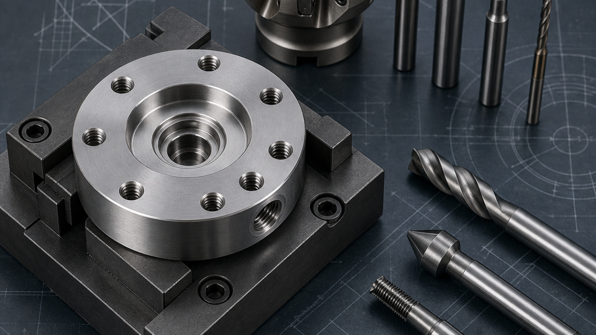
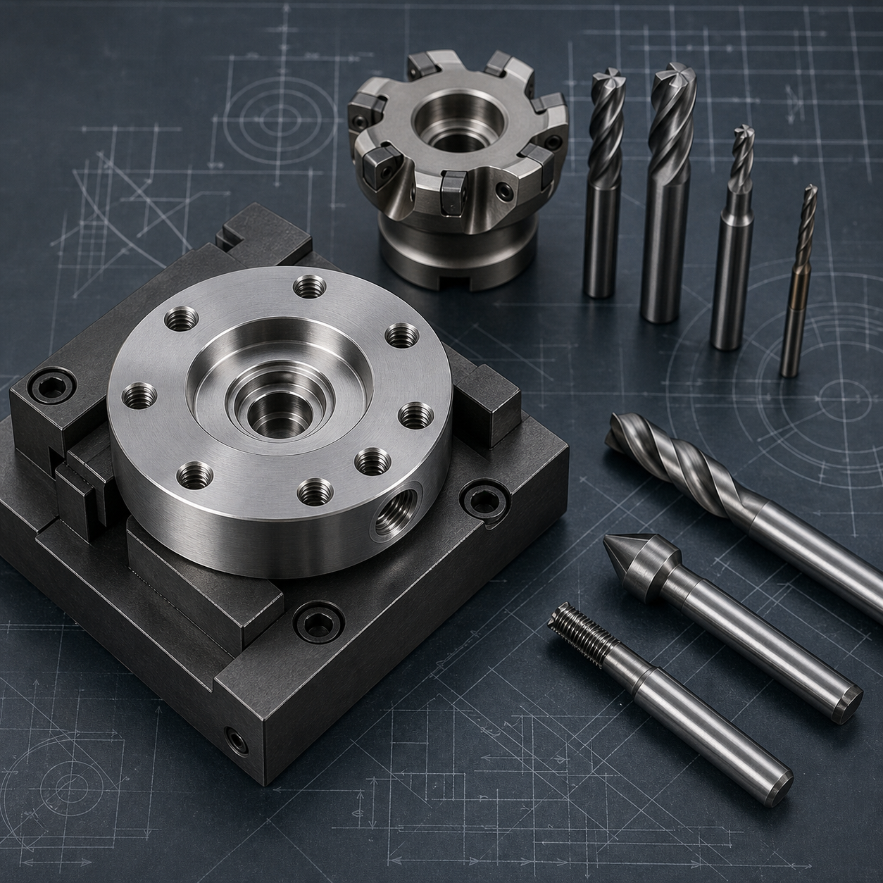
This hypothetical case starts with a 15-5PH stainless pressure-sensor flange made from solution-treated stock. The drawing calls for a central stepped bore, a shallow rear diaphragm pocket, a circular sealing land, a bolt circle, one radial pressure port and controlled flatness between the mounting and sealing faces. The manufacturing risk is not simply material removal: the thin diaphragm can move after roughing, while the sealing land must remain clean and concentric to the functional bore.
Datum and fixture plan
Use the broad mounting face as primary datum A, the stepped bore as datum B and one bolt-circle feature as clocking datum C. Rough the blank in soft jaws, leaving balanced stock on both faces. After stress is released, finish the bore and sealing face in one clamping. For the reverse operation, use a relieved nest that supports the flange rim without loading the diaphragm area.
Tool-to-feature selection
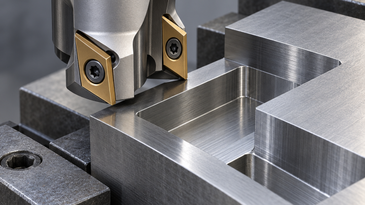
- A positive-rake carbide face mill establishes datum A with low axial force.
- A variable-helix carbide end mill roughs the diaphragm cavity with constant engagement and a conservative axial step.
- A short-reach corner-radius end mill semi-finishes the pocket; a fresh sharp finisher leaves the final diaphragm thickness.
- A pilot drill followed by a carbide drill and thread mill produces the radial port while avoiding tap breakage in stainless steel.
- A 90-degree carbide chamfer tool breaks only specified edges and protects the sealing land.
Process sequence and quality control
Rough both sides before final sizing, allow the part to stabilize, then finish the bore, face and sealing land together. Use climb milling, consistent coolant delivery and reduced radial engagement to limit work hardening. Probe the bore position before machining the bolt circle. Inspect diaphragm thickness at several points, face flatness on a controlled support, bore size and port location. Surface finish should be verified on the sealing land, not inferred from tool marks.
Related reading: 17-4PH clevis bracket datum and cross-hole planning and CNC toolpath smoothing for surface finish.