This is a hypothetical tooling decision guide, not a claim about a customer project or verified production result.
English: Low-Runout Tool Holders for Carbide End Mills: Measure, Diagnose and Correct TIR
A low-runout tool holder is not proved by a catalog number. It is proved by total indicated runout (TIR) at the assembled cutting tool, at the working projection, after the taper and clamping parts are clean. For a four-flute carbide end mill, even a small eccentricity makes one edge carry more chip load, so tool life and wall finish can fail before the programmed feed looks aggressive.
Build a runout budget from spindle to cutting edge
Read the drawing for cutter diameter, usable flute length, corner access, wall finish and reach. Then allocate error among spindle taper, holder interface, collet or bore, cutting-tool shank and projection. Check the bare spindle with a certified test arbor first; otherwise a holder change may appear to cure a dirty taper.
Match holder type to the drawing feature
A 12 mm variable-helix rougher in a rigid pocket can use a milling chuck or quality shrink-fit holder because grip and pull-out resistance dominate. A 3 mm end mill for narrow ribs favors a precision hydraulic or shrink-fit holder with minimal projection. A long-reach wall-finishing tool needs a damped, slim hydraulic holder if clearance permits. A standard ER system remains practical only with a precision collet, correct nut, controlled torque and no excessive reduction sleeve.
Application-to-holder decision map
| Drawing feature | Carbide tool and holder | Why / rejection |
|---|---|---|
| 12 mm adaptive pocket roughing | 4–5 flute variable-helix carbide; shrink-fit or power chuck; short reach | Grip and pull-out resistance; reject a worn general-purpose collet |
| 3 mm micro slot and rib | 2–3 flute micrograin carbide; precision hydraulic or shrink-fit | Low TIR and gentle clamping; reject stacked reduction sleeves |
| Tall finish wall | 5 flute relieved-neck finisher; slim hydraulic holder | Damping and clearance; reject unnecessary projection |
| Production hole chamfer | 3 flute carbide chamfer mill; precision ER collet | Economical when TIR is verified and torque controlled |
Measure before changing cutting parameters
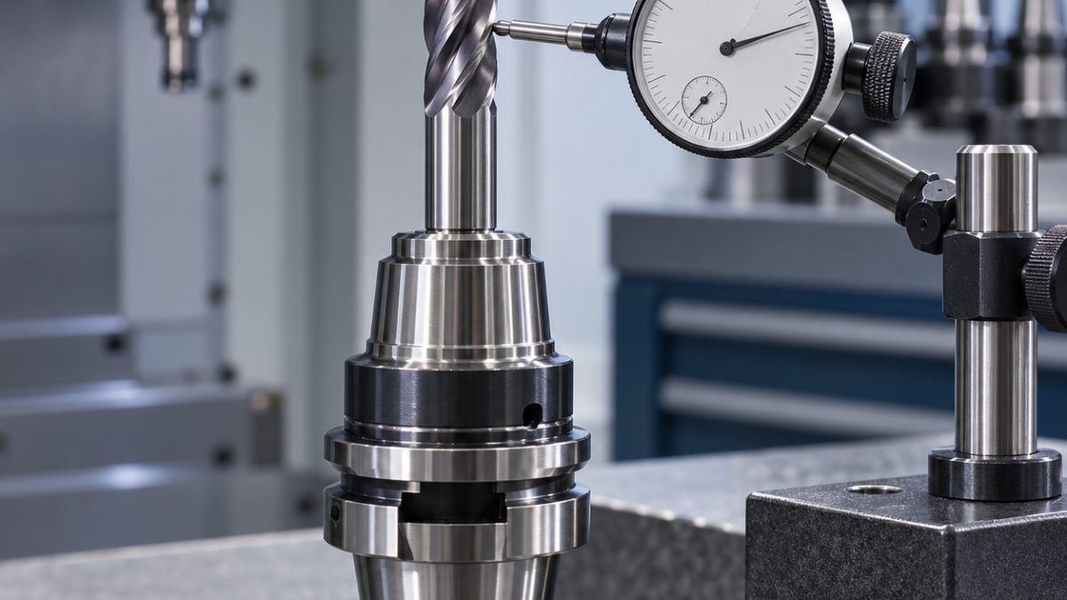
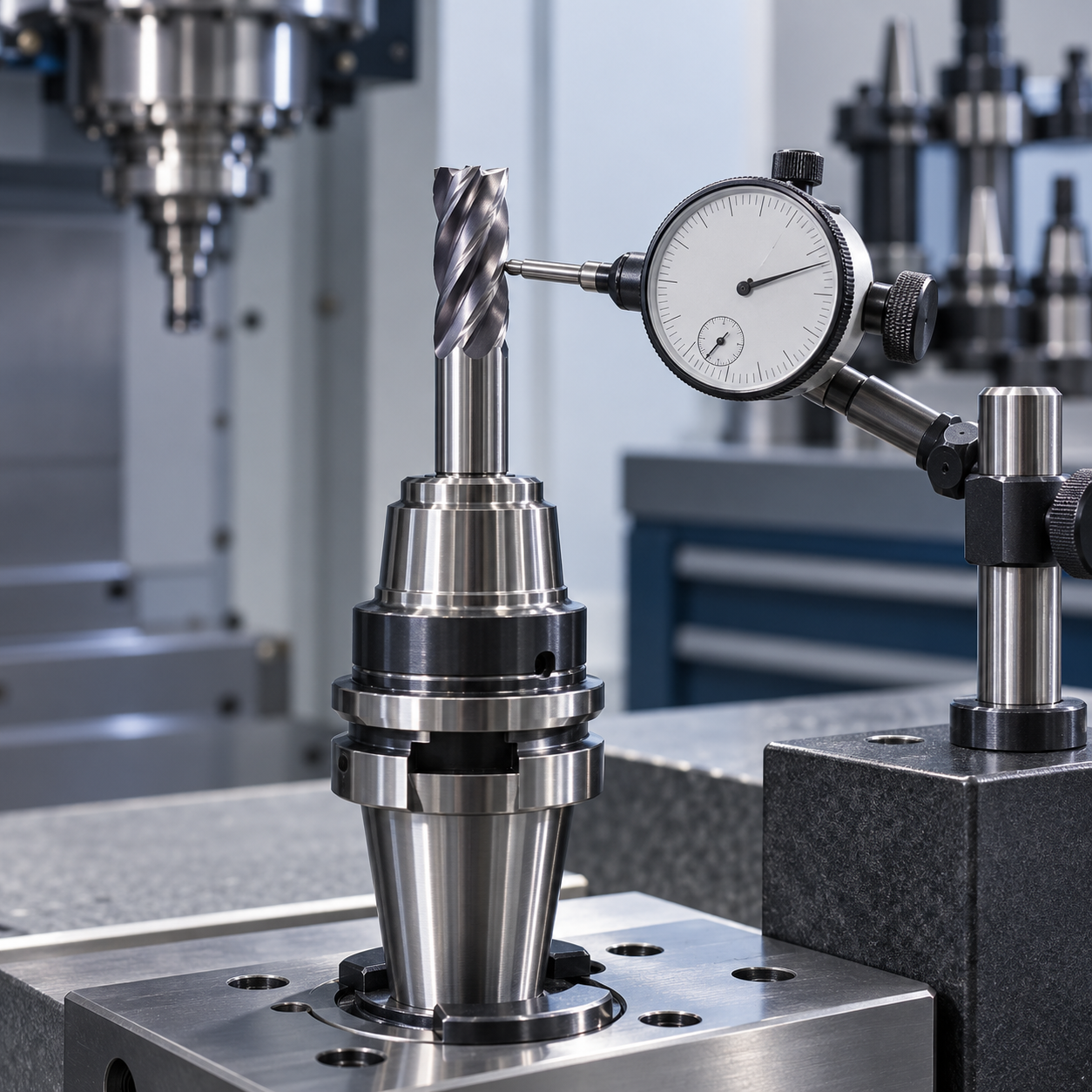
Measure on a ground tool shank and again near the cutting diameter, commonly at about three tool diameters from the gauge line or at the actual working reach. Rotate the complete assembly slowly with a 0.001 mm indicator. Mark high points, reseat once, and record TIR; do not average away a repeatable lobe. Balance grade controls rotating mass distribution, while runout controls cutting-edge orbit: one cannot certify the other.
Face milling adds a different check: compare the axial position of the mounted cutting edges, not just radial TIR. The SEKT1204 case for separate mounting pads explains how insert-height differences and cutter overlap enter a flatness decision even when the arbor itself runs true.
On an indexable shoulder mill, a concentric shank still does not prove that all insert corners generate the same wall and floor. Use the R390 11T3 locating-shoulder example to connect cutting-edge checks with the drawing’s permitted corner radius and the remaining stock before the finishing pass.
Correct the assembly without hiding the cause
Clean taper, holder bore, collet and shank without abrasive polishing. Replace fretted collets and damaged nuts, respect minimum clamping length, and use the specified torque wrench or heating cycle. Shorten overhang before reducing feed. If the high point follows the cutter, inspect its shank; if it follows the holder, quarantine the holder; if all holders repeat the same angular error, inspect spindle and taper.
If a legacy cutter repeatedly shows one high insert after cleaning, inspect seat geometry, support and clamping before replacing the holder. The TPKN2204 cutter-body matching example separates these assembly checks from a simple triangular-outline comparison; a familiar insert code is not proof that the pocket and clamp are correct.
Related technical cases: Shrink-fit holder stability; micro end-mill selection; carbide cutting parameters.
FAQ
Where should tool-holder runout be measured? At the assembled tool and the actual cutting reach, after a spindle/test-arbor baseline.
Is 0.003 mm TIR acceptable? It depends on tool diameter and tolerance. It may be manageable on a 12 mm rougher but severe for a 1 mm cutter.
Can balancing fix runout? No. Balancing corrects mass distribution; it does not center the cutting edges.
Inspection closes the loop: record TIR, pocket wall waviness, tool wear by flute and finished size. A single chipped flute paired with a repeatable TIR high point is evidence of load imbalance, not a reason to lower every cutting parameter.


