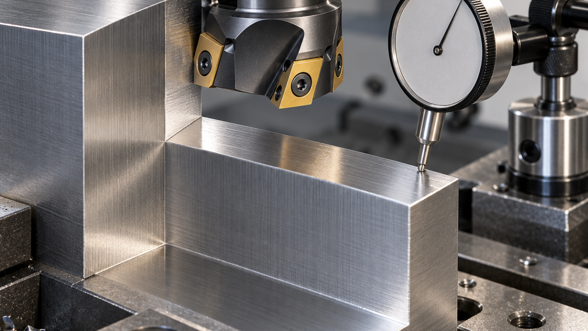
English: R390 11T3 Inserts: Corner Radius for Square-Shoulder Finishing
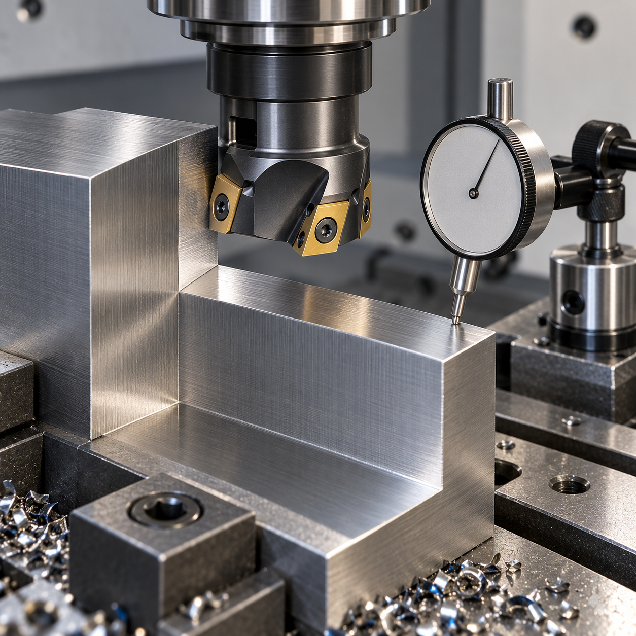
Choose an R390 11T3 insert radius from the mating-part clearance before choosing it for edge strength. On a square locating shoulder, the largest robust corner is not necessarily acceptable. This hypothetical stainless positioning block has two perpendicular ledges, each 6 mm high, with a maximum root radius of 0.5 mm. A nominal R0.4 candidate can fit that requirement; an R0.8 candidate cannot. The insert’s complete suffix and cutter compatibility still require confirmation.
The shoulder is an assembly interface
Assume annealed 316L, ledge height ±0.015 mm, perpendicularity 0.03 mm to the underside datum and contact-surface Ra 1.6 μm. These are study targets, not claimed production results. Leave accessible relief beyond each contact strip so the tool can exit without dwelling. Sandvik’s R390 product family is a square-shoulder system; the shorthand “R39011” does not identify one radius, geometry or grade. Do not mix size 11 with size 17 seats.
One body, different cutting duties
| Interface | Selection | Reason |
|---|---|---|
| Initial ledge stock | Ø20 shoulder body approved for size 11 inserts; moderate tooth count, tough carbide grade recommended for ISO M, PVD option where offered. | A reinforced medium geometry can rough, but must not leave a torn work-hardened skin. |
| Root ≤R0.5 and contact wall | R390 11T3 R0.4 variant, positive finishing-compatible geometry, controlled light edge preparation; minimum practical projection. | R0.8 is rejected even if it lasts longer, because assembly clearance governs. |
| Small end relief | Ø6, four-flute stainless-capable carbide end mill, short flute length and stable collet or hydraulic holder. | The larger body cannot reach the end geometry without overtravel into another datum. |
| Outer burr | Ø6 carbide chamfer mill with two flutes, 90°, local edge break only. | Keep the contact wall and specified root intact. |
Separate the wall cut from the floor witness mark
Clamp on the thick base, support below both ledges, rough them symmetrically and leave a trial 0.10–0.15 mm radial stock. Establish a continuous final wall pass with a stable chip thickness. Repeated near-zero spring passes in 316L can rub rather than correct geometry. Use the chosen cutter’s limits for ramping and axial depth; do not infer them from the insert code.
Before the finishing pass, measure each insert’s axial and radial position. A chip under one seat can create a polished floor and still leave a tapered wall. Clean the seats, inspect the screw bearing surfaces and use specified torque. Maintain consistent directed coolant to remove stringy chips; avoid recutting them against the finished wall. Built-up material or notch wear at the shoulder height is a reason to inspect the edge before offset correction.
Measure a relationship, not just a width
Probe each wall at low and high positions relative to datum A, check both ledge heights, then evaluate the root with an optical method or a suitable profile replica. A caliper cannot establish perpendicularity. Measure roughness along the functional contact direction and inspect the exit for rolled burrs. See insert assembly runout principles and controlled edge breaking.
Questions about R390 ordering
Is the number 04 enough to order? No. Confirm the complete maker’s designation, geometry, grade and compatible body; this example uses a verified nominal radius, not a universal shorthand rule.
Can offset compensation fix a large root radius? No. Moving the tool to correct the wall does not make its corner smaller and can damage the floor.
Manufacturer reference: dimensions and system compatibility.


