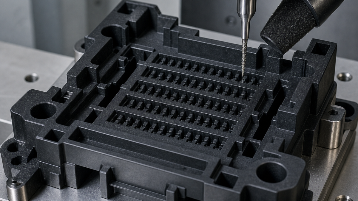
English: PBT-GF30 Connector Inspection Nest CNC Tool Selection for 0.60 mm Pin Pockets
A PBT-GF30 connector inspection nest fails when the tool leaves glass-fiber fuzz inside a 0.60 mm pin pocket or bends a latch wall that looks correct while clamped. The useful tooling answer combines diamond-coated carbide for abrasive walls, a polished low-helix finisher for the contact floors, and a fixture that supports the nest under every functional rail. This hypothetical case maps each drawing feature to a cutter and a verification method instead of treating glass-filled polymer as ordinary plastic.
The connector decides which dimensions matter
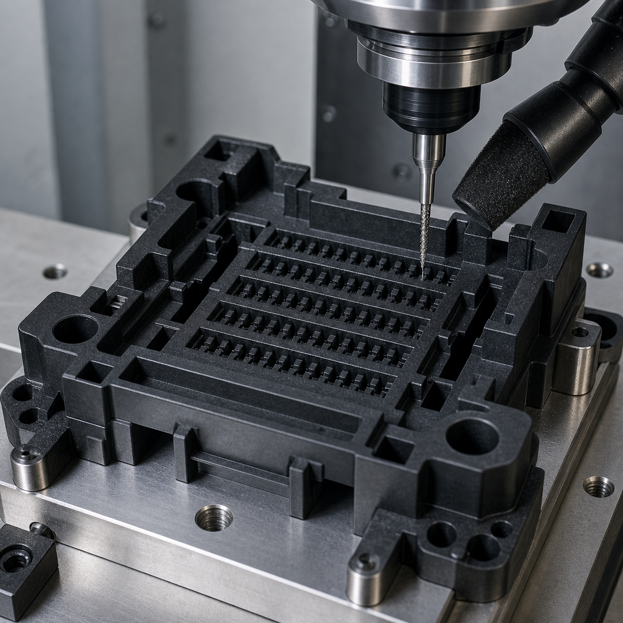
Bottom face A seats on the inspection machine; Ø6 H7 bore B and a 6 mm slot C orient the nest. The centre field holds 48 rectangular pin pockets, each 0.600 +0.020/0 mm wide, 1.20 ±0.02 mm long and 6.00 ±0.03 mm deep, with true position 0.025 mm to A|B|C. Two latch windows are 1.50 ±0.03 mm wide. Four support rails stand 0.70 ±0.025 mm above the pocket floor, and the outer nest contour must leave 0.10–0.20 mm assembly clearance to a qualified master connector. Continuous fiber whiskers, a melted glaze or a raised floor burr are rejected.
The 30% glass-filled PBT designation describes a material family, not a single cutting behaviour. Fiber length, molding orientation, moisture conditioning and annealing can change breakout. Incoming blanks therefore include orientation marks, and the first-piece plan is qualified in both the strong and weak edge directions.
Feature-to-tool register with a quality signal
| Feature | Carbide selection and holder | Quality signal during cutting |
|---|---|---|
| A face and outside envelope | Ø10 two-flute diamond-coated carbide router, 20° compression geometry, 0.02 mm edge radius, short hydraulic chuck | Balanced top and bottom shear limits fiber lift. A bright glazed track indicates rubbing or excessive heat. |
| Large relief cavities | Ø4 three-flute diamond-coated carbide end mill, 30° variable pitch, R0.2, 10 mm reach, through-air shrink holder | Stable spindle load and short granular chips show adequate chip thickness; long softened strings trigger a feed and extraction check. |
| 0.60 mm pin pockets | Ø0.50 two-flute diamond-coated carbide micro end mill, 15° low helix, 6.5 mm necked reach, 4 µm edge preparation, ultra-precision shrink collet | Width is created by two compensated wall passes, not full slotting. Growing width taper or a fuzzy exit photograph retires the tool. |
| Pocket floors | Ø0.45 single-flute uncoated polished O-geometry carbide, R0.03, 1.0 mm cutting length on a 6.2 mm relieved neck | The uncoated sharp edge skims 0.015 mm from the floor without dragging fiber. It is protected from wall roughing, where glass would wear it rapidly. |
| 1.50 mm latch windows | Ø1.2 two-flute diamond-coated compression carbide, 18° helix, 5 mm flute length, HSK-E25 shrink holder | Alternating shear supports both window faces. A high-helix general end mill can pull the thin latch wall upward. |
| Ø6 H7 datum B | Ø5.7 two-flute diamond-coated carbide drill, 130° point, backed exit; then Ø6 four-flute PCD-tipped straight reamer | The reamer establishes a stable coordinate bore. Interpolation with a worn pocket tool would couple datum size to array wear. |
| Slot datum C | Ø3 four-flute diamond-coated carbide, 25° helix, 5 mm flute length; two opposed finish passes | Opposed passes expose directional fiber breakout before C is accepted. |
| 0.08 mm edge breaks | Ø2 three-flute PCD chamfer mill, 60° included angle, 0.08 mm programmed width | Controlled cutting removes whiskers. Flame polishing and abrasive brushing are rejected because they distort pockets and contaminate floors. |
Route verified by a master, not by appearance alone
The fixture is an aluminium nest with replaceable polymer support buttons beneath A, the four rails and both latch zones. Two side keys locate the blank without squeezing it; a broad top plate clamps only the sacrificial perimeter. A is skimmed first, then B and C are finished and probed. Large reliefs are roughed from the centre outward while the pin field remains solid.
The 48 pockets are not processed as a heat map. Instead, the program follows connector function: ground contacts, signal contacts, then latch-adjacent contacts, allowing a qualified master to test each group before the next is opened. The Ø0.50 tool enters by a small helical ramp, roughs at constant engagement and leaves 0.012 mm per wall. It then makes one climb-finish pass per side. The separate O-flute tool touches only the pocket floors.
Point extraction is positioned beside the cut so glass-filled chips do not recut or spread through the machine. Cool air may be used if it is dry, clean and validated for static control; uncontrolled compressed-air blow-off is avoided. Tool life is governed by microscope images of the same reference corner, pocket-width trend, spindle load and master insertion force—not by a fixed number copied from another PBT grade.
Inspection includes functional compliance
A vision CMM measures B-C, pocket centres, widths and latch-window edges. A low-force confocal or white-light method checks floor depth and the 0.70 mm rails without compressing them. The released nest is placed on three points to verify A and rail height, then seated on its intended support for a second map. A qualified master connector is inserted at controlled speed; insertion force and full-seat position confirm the combined clearance but do not replace dimensional inspection.
Which cutter is suitable for 0.60 mm pockets in PBT-GF30?
A Ø0.50 low-helix diamond-coated carbide micro end mill leaves room to compensate both walls and resists glass-fiber abrasion.
Why use an uncoated O-flute tool on the pocket floor?
It is reserved for a very light floor skim where the sharp polished edge prevents smearing; exposing it to abrasive wall roughing would shorten its life.
How should fiber fuzz be removed from connector pockets?
Prevent it with compression or low-helix cutting and sharp controlled chamfers. Manual brushing or heat polishing can move material into the tolerance zone.
Related guides: composite dust and edge control and micro-end-mill breakage prevention.


