This is a realistic hypothetical process-planning example, not a claim about a specific customer drawing or production result.
Related: Read the related CNC tooling case.
English: CNC Thread Milling Large Internal Threads: Pitch Diameter Compensation and Gauge Control
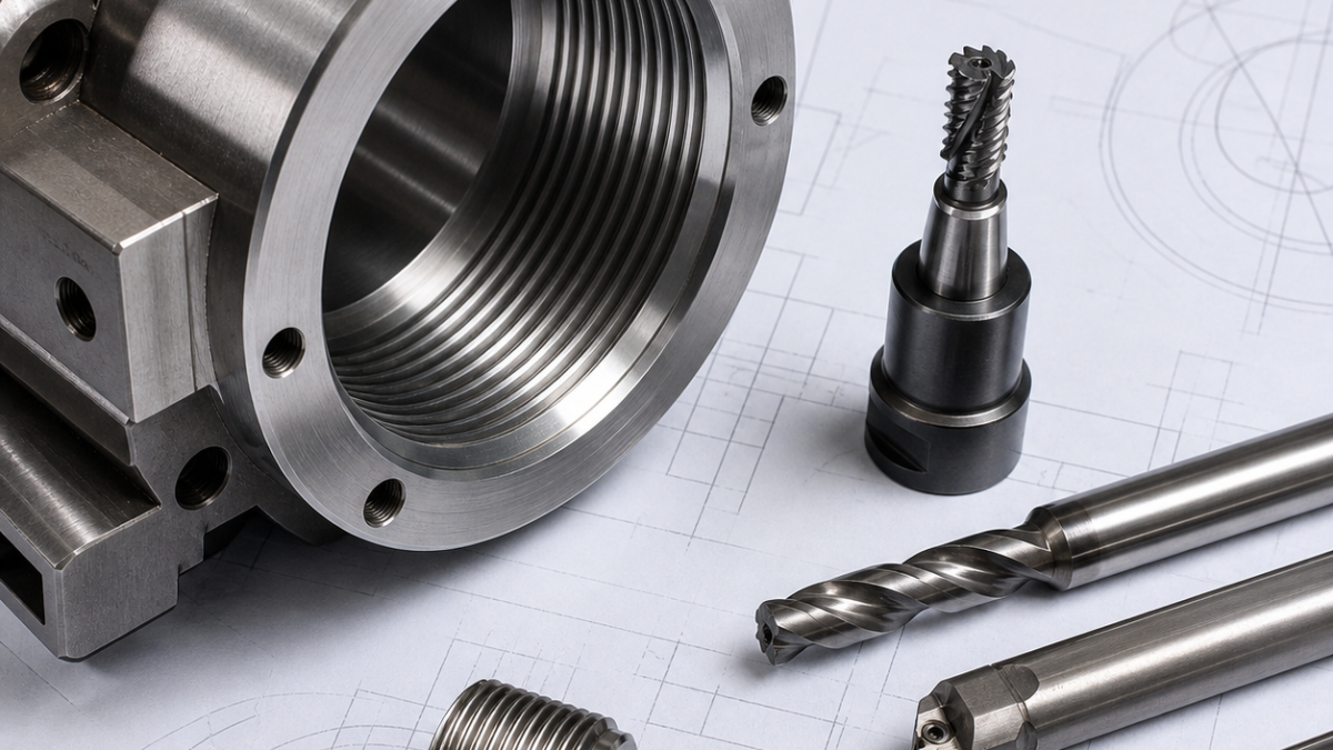
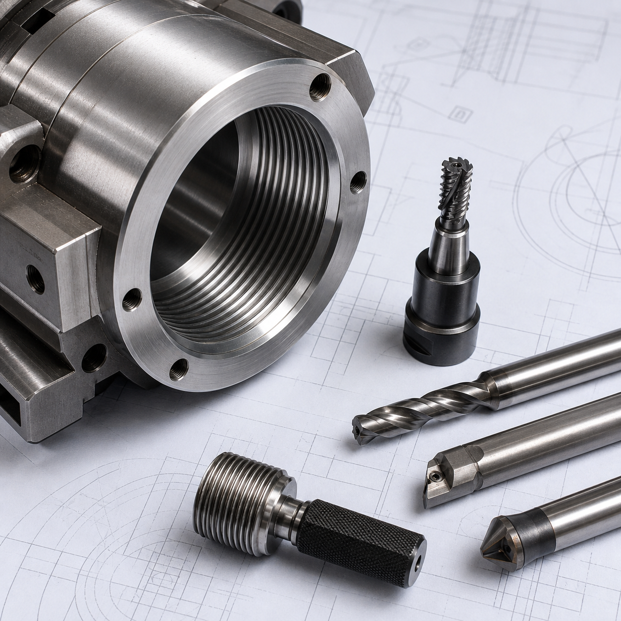
This hypothetical actuator housing uses a large blind internal thread close to a sealing face. Thread milling is selected over tapping because torque, chip evacuation and pitch-diameter adjustment matter more than raw cycle time. The long-tail search intent is how to reach a functional gauge fit without damaging an expensive part.
Feature and datum interpretation
This hypothetical actuator housing uses a large blind internal thread close to a sealing face. Thread milling is selected over tapping because torque, chip evacuation and pitch-diameter adjustment matter more than raw cycle time. The long-tail search intent is how to reach a functional gauge fit without damaging an expensive part.
Tool selection and cutting strategy
Bore the minor diameter with a stable boring bar and machine the entry relief and chamfer first. Choose a carbide thread mill with enough flute length but minimum neck overhang. A multi-row cutter is fast and rigid; a single-row cutter is flexible for different pitches and reduces cutting load.
Fixture and process sequence
Program a helical path with climb cutting, a tangential lead and verified radial clearance. Start with conservative wear compensation, measure the first part, then adjust radius by a controlled fraction of the gauge error. Use a spring pass only if deflection is repeatable, not as a substitute for a worn tool.
Tolerance, surface and tool-life risks
Check pre-bore size, pitch diameter, entry form and bottom clearance. Clean chips before using the GO/NO-GO gauge and never force it. Track compensation history by tool edge; a sudden correction increase indicates wear, runout or material buildup.
FAQ
What should be verified first?
The drawing datum, actual stock and tool runout must be confirmed before compensation.
Can one gauge prove the whole feature?
No. Functional gauging should be combined with dimensional and positional inspection.


