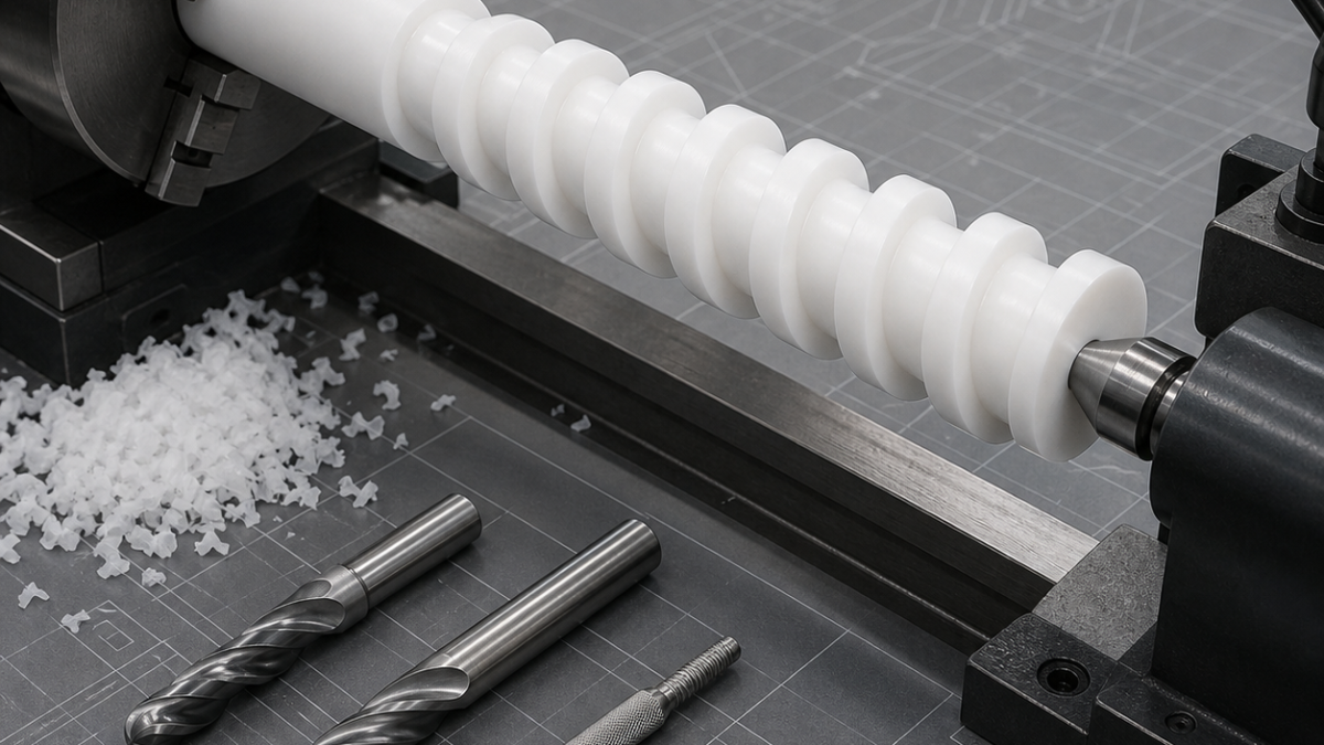
This is a realistic hypothetical process-planning example, not a claim about a specific customer drawing or production result.
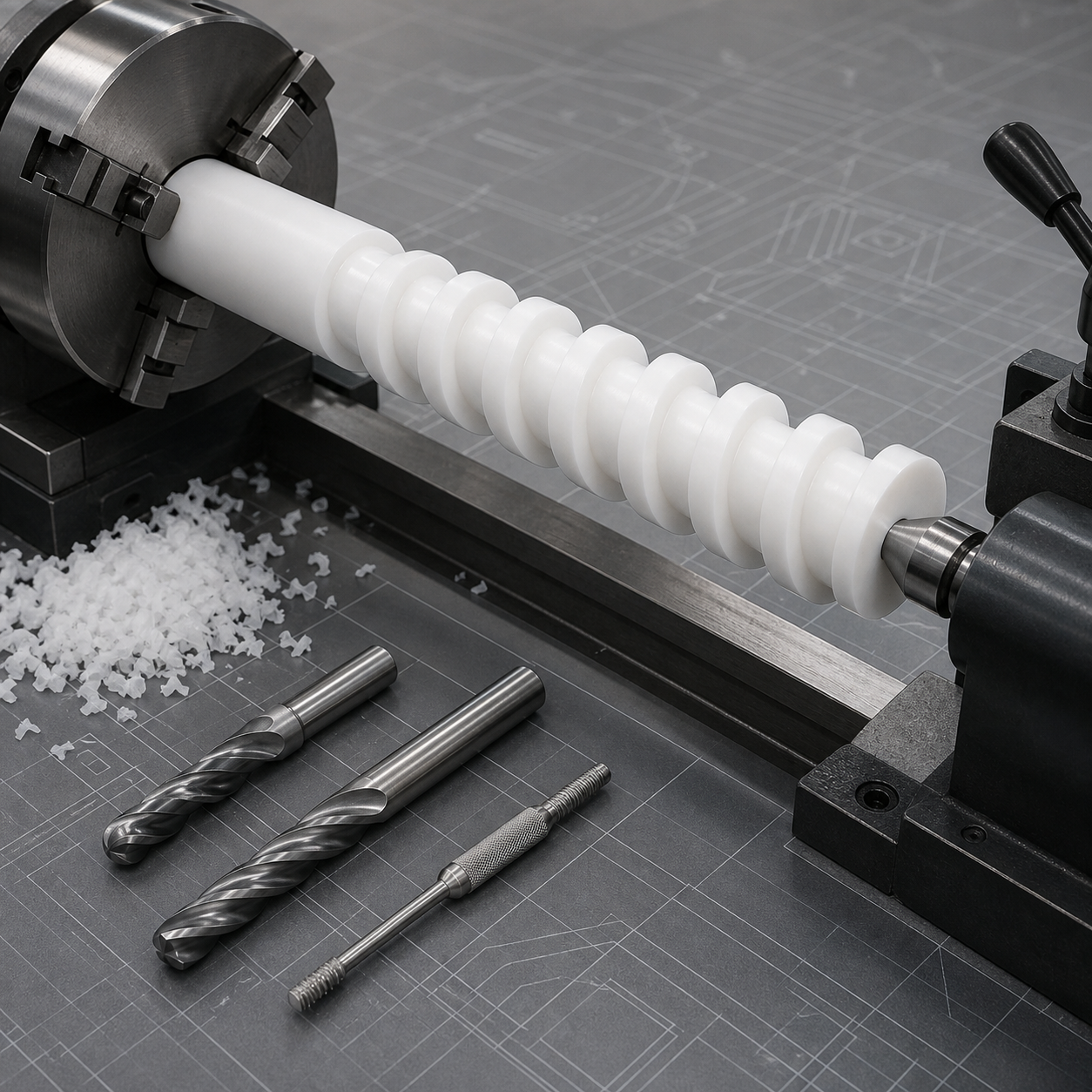
Related: Compare polymer burr control in the PEEK manifold case and long-part stability principles in the residual-stress guide.
English: reading the UHMWPE metering-screw drawing
This hypothetical part has a long bearing journal, a deep helical metering channel, changing root diameter, controlled crest width and end drive features. The drawing should be interpreted as a functional profile: pitch, root depth, crest thickness and runout to the journals interact with feed consistency and cannot be inspected as isolated dimensions.
Datums and feature map
Use the two finished journals to define the rotating axis and an end face to clock the helical start. Mark the root transition and channel exit as burr-critical zones. Confirm whether profile tolerance applies in the free state and whether the lead is constant or intentionally variable before programming rotary interpolation.
Sharp carbide tool package
Turn journals with a polished positive-rake insert. Rough the channel with a short sharp carbide end mill where access permits, then use a reduced-neck ball-nose or radiused end mill for the root and sidewalls. A dedicated plastic-cutting chamfer tool should break edges without pushing a feather burr back into the channel.
Support and toolpath sequence
Keep generous support diameters while establishing journals, then mount between a collet and live center or on a rigid rotary support. Rough the helix in multiple constant-engagement passes, alternating axial zones to limit heat. Finish both channel flanks from the same rotary datum, then complete end features and remove support stock with low clamping force.
Chip, heat and inspection risks
UHMWPE produces continuous stringy chips that can wrap around the part and re-cut the surface. Use polished flutes, air evacuation or approved coolant, and programmed chip-clearing retracts without dwelling on the finish wall. Inspect lead and root profile on a rotary scan or sampled sections after temperature stabilization; high clamping force can temporarily hide straightness error.
FAQ
Why not use one full-depth form cutter?
A wide form cut raises force, heat and chip-packing risk; staged milling gives better profile correction and evacuation.
Should feeds be reduced to prevent melting?
Not automatically. Too little chip thickness causes rubbing; use a sharp edge, real chip load and effective evacuation.


