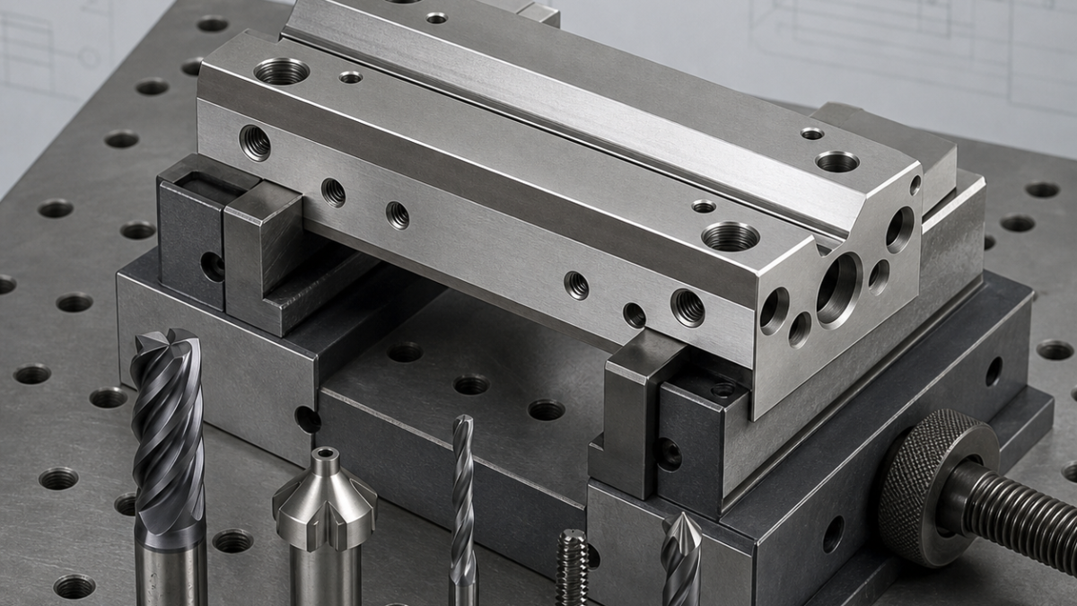
This is a realistic hypothetical process-planning example, not a claim about a specific customer drawing or production result.
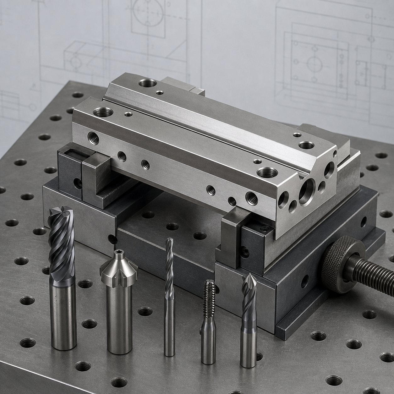
Related: See the 304 stainless groove-tooling case and our variable-helix end-mill guide.
English: reading the actuator guide-block drawing
This hypothetical Nitronic 60 block uses an angled dovetail as the working guide, intersecting lubrication grooves, precision mounting bores and tapped cross ports. The drawing links rail angle, rail width and mounting datum parallelism; these must be controlled as a system while avoiding heat and galling.
Translate drawing features into controls
Establish the mounting bottom as datum A, one long side as B and a dowel bore as C. Measure the dovetail by functional rollers or a matched master rather than relying only on the sharp virtual corners. Identify groove intersections as burr-critical features and specify which port must break through first.
End mills, dovetail cutter and hole tools
Use a variable-helix carbide end mill for roughing, leaving equal stock on both rail faces. Semi-finish with a rigid necked end mill, then use a dedicated carbide dovetail cutter for the final angle. Carbide drills, a thread mill and a small ball or lollipop cutter address cross ports and lubrication channels without high tapping torque.
Fixture and toolpath strategy
Face the datum set in a rigid vise, rough the upper geometry with constant radial engagement, and finish the mounting bores before the final rail cut. Refixture on hardened pads using the bores, then machine the dovetail in alternating passes so one side does not heat disproportionately. Open oil grooves last with supported entry and exit moves.
Tolerance, surface finish and galling risk
Nitronic 60 resists galling in service but still work-hardens in machining. Keep chip thickness above rubbing level, use strong coolant delivery and avoid dwelling at dovetail ends. Inspect rail width after thermal equalization. A worn dovetail cutter changes both angle and finish, so monitor cutting load and retire it before flank wear becomes a geometry error.
FAQ
Why not cut the dovetail to size in one pass?
A full-width cut creates high heat, deflection and asymmetric tool wear; staged balanced passes are easier to control.
Are taps suitable for the cross ports?
They can be, but thread milling lowers torque and makes chip evacuation and size correction safer.
中文:解读 Nitronic 60 执行器导向块图纸
本假设导向块以斜燕尾面作为工作导轨,同时包含相交润滑槽、精密安装孔和横向螺纹油口。图纸把导轨角度、跨距与安装基准平行度联系在一起,加工时需要作为整体控制,并避免切削热和黏着。
把图纸特征转为控制项目
底部安装面设为基准 A,长侧面设为 B,定位销孔设为 C。燕尾跨距宜用量棒或配对检具评价,不能只依赖理论尖角。润滑槽交叉口应标记为毛刺关键区,并明确横孔的贯通顺序。
立铣刀、燕尾刀和孔加工刀具
变螺旋硬质合金立铣刀用于粗加工,并在燕尾两面保留等量余料;高刚性缩颈刀完成半精加工,专用硬质合金燕尾刀最后形成角度。横孔和油槽采用硬质合金钻头、螺纹铣刀及小球头或棒棒糖刀,降低攻丝扭矩和交叉孔毛刺。
夹具与刀路策略
先在刚性虎钳中建立基准,使用恒定径向负载刀路粗铣上部特征,并在导轨精加工前完成定位孔。再用定位孔和硬化支承块重装,燕尾两侧交替进刀,避免单侧过热。润滑槽最后加工,入口和出口都应有支承。
公差、表面与黏着风险
Nitronic 60 服役时抗咬合,但切削时仍容易加工硬化。切屑厚度必须高于擦削区,冷却液要直接到刃口,燕尾末端不能停顿。工件温度稳定后再检查跨距;燕尾刀后刀面磨损会同时改变角度和表面,应通过负载趋势提前换刀。
常见问题
为什么不能一刀完成燕尾槽?
满宽切削会产生较高热量、挠度和不对称磨损,分阶段平衡加工更容易控制。
横向油口能否直接攻丝?
可以,但螺纹铣削扭矩更低,排屑和中径补偿也更安全。
Français : lire le plan du bloc-guide en Nitronic 60
Ce bloc hypothétique associe une glissière en queue d’aronde, des rainures de lubrification, des alésages de montage et des ports filetés. L’angle, la largeur fonctionnelle et le parallélisme à la base doivent être pilotés ensemble.
Références et contrôles
La face inférieure devient A, le long côté B et un alésage de pion C. Mesurer la queue d’aronde sur piges ou avec un calibre fonctionnel et traiter chaque intersection de rainure comme zone critique de bavure.
Choix des outils
Une fraise carbure à hélice variable ébauche en laissant une surépaisseur égale. Une fraise à col rigide prépare les flancs, puis une fraise à queue d’aronde dédiée finit l’angle. Forets carbure et fraise à fileter complètent les ports.
Montage et trajectoires
Créer les références en étau rigide, ébaucher à engagement constant, puis reprendre sur les alésages et des appuis trempés. Finir alternativement les deux flancs et ouvrir les rainures d’huile en dernier.
Risques de surface et d’usure
Maintenir une épaisseur de copeau réelle, arroser directement et éviter les pauses. Contrôler la largeur après stabilisation thermique; l’usure de la fraise spéciale modifie à la fois angle et rugosité.
FAQ
Pourquoi plusieurs passes équilibrées ?
Elles limitent chaleur, flexion et usure asymétrique.
Pourquoi fraiser les filets ?
Le couple est plus faible et le diamètre peut être compensé.
Русский: анализ чертежа направляющего блока Nitronic 60
Условный блок содержит рабочую ласточкину направляющую, канавки смазки, точные установочные отверстия и поперечные резьбовые каналы. Угол, функциональная ширина и параллельность к основанию контролируются совместно.
Базы и контроль
Нижняя плоскость служит базой A, длинная сторона — B, отверстие под штифт — C. Направляющую измеряют по роликам или функциональным калибром, а пересечения канавок считают зонами риска заусенца.
Набор фрез и сверл
Фреза с переменной спиралью черновит с равным припуском, жесткая шейковая фреза выполняет получистовую обработку, специальная твердосплавная фреза формирует угол. Каналы заканчивают сверлами и резьбовой фрезой.
Установ и траектория
Базы создают в жестких тисках, затем деталь переустанавливают по отверстиям на закаленные опоры. Стороны направляющей чистят попеременно, канавки смазки открывают последними.
Риски поверхности и стойкости
Нельзя допускать трения и остановок. Требуются стабильная толщина стружки и направленная СОЖ. Износ специальной фрезы меняет угол, поэтому его отслеживают по нагрузке.
FAQ
Почему не обрабатывать за один проход?
Полный контакт повышает нагрев, прогиб и неравномерный износ.
Можно ли применять метчик?
Можно, но резьбовая фреза снижает момент и упрощает удаление стружки.


