Related tooling references: AM 316L Hydraulic Valve Block CNC Tool Selection for Printed Datum Cleanup and Deep O-Ring Ports and PEEK-GF30 Rotary Valve Rotor CNC Tool Selection for Seal Lands and Curved Metering Slots.
English: Zerodur Mirror Cell Tooling for Lightweight Pockets and Bond Pad Flats
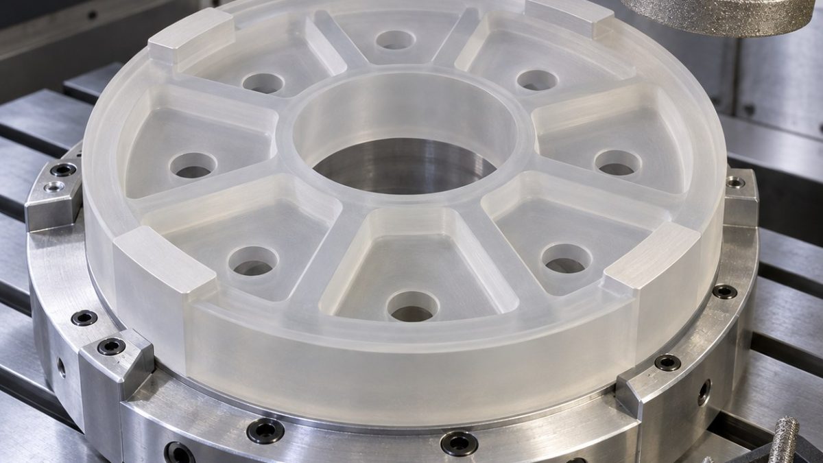
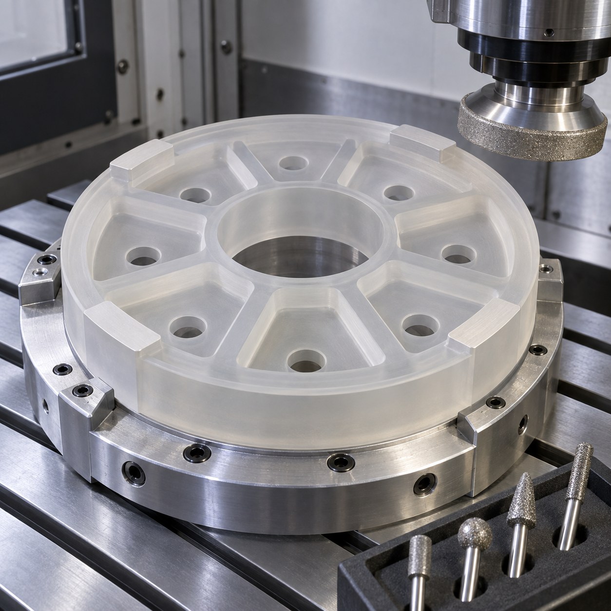
This case answers a narrow long-tail question: which diamond tools fit a Zerodur mirror cell drawing when light weighting and bond-pad flatness must survive release. The datum logic is not metal milling logic; the drawing asks for controlled abrasion, low clamp force and chip-free edges.
Drawing risk read before choosing diamond tools
| Drawing feature | Selected tool and holder | Why this choice wins |
|---|---|---|
| Lightweight pocket webs | 6 mm metal-bond diamond router in low-runout shrink holder | A carbide mill is rejected because rubbing raises microcracks instead of clean grinding. |
| Bond pad flats | 20 mm fine-grit diamond cup wheel on a balanced arbor | Keeps pad height consistent without point loading fragile ribs. |
| Vent holes | Ultrasonic diamond core drill with wax support | Prevents exit breakout; a twist drill has no useful cutting edge in Zerodur. |
| Outer datum rim | Fine diamond peripheral wheel, climb grinding only after rough relief | Avoids edge pullout before the pockets release stress. |
| Final edge break | Small resin-bond diamond chamfer pin | Creates a matte safety chamfer without hand-stone corner chips. |
Low-force sequence and vacuum support
Start with a wax-backed support plate and only light vacuum. Rough relief pockets are ground with stock left at the rib roots, then vent holes are cored before the bond pads are finished. Pad grinding happens after a thermal dwell so the final height is not copied from a stressed setup.
Edge-chip and subsurface-damage controls
Zerodur dust is abrasive and the risky defect is a barely visible edge chip. Coolant flow is kept clean, tool runout is checked before each pad pass, and diamond tools are retired when the edge starts producing frosted corners rather than a predictable matte grind.
Metrology for released optical geometry
Inspection uses a flatness map over the bond pads, optical edge review at pocket transitions, pin-gauge checks on vent holes and a released-state repeat after the vacuum is removed. The acceptance decision is pad coplanarity plus zero functional chips near bonding zones.
Practical FAQ
Can Zerodur be cut with ordinary carbide end mills?
For rough shaping it may remove material, but this drawing needs controlled grinding; ordinary carbide raises chip and microcrack risk near bond pads.
Why finish the bond pads after vent holes?
The holes can release local stress and create minor support change, so the pads are the final functional surface.
What is the inspection priority?
Released pad coplanarity and chip-free bonding edges matter more than cosmetic pocket texture.


