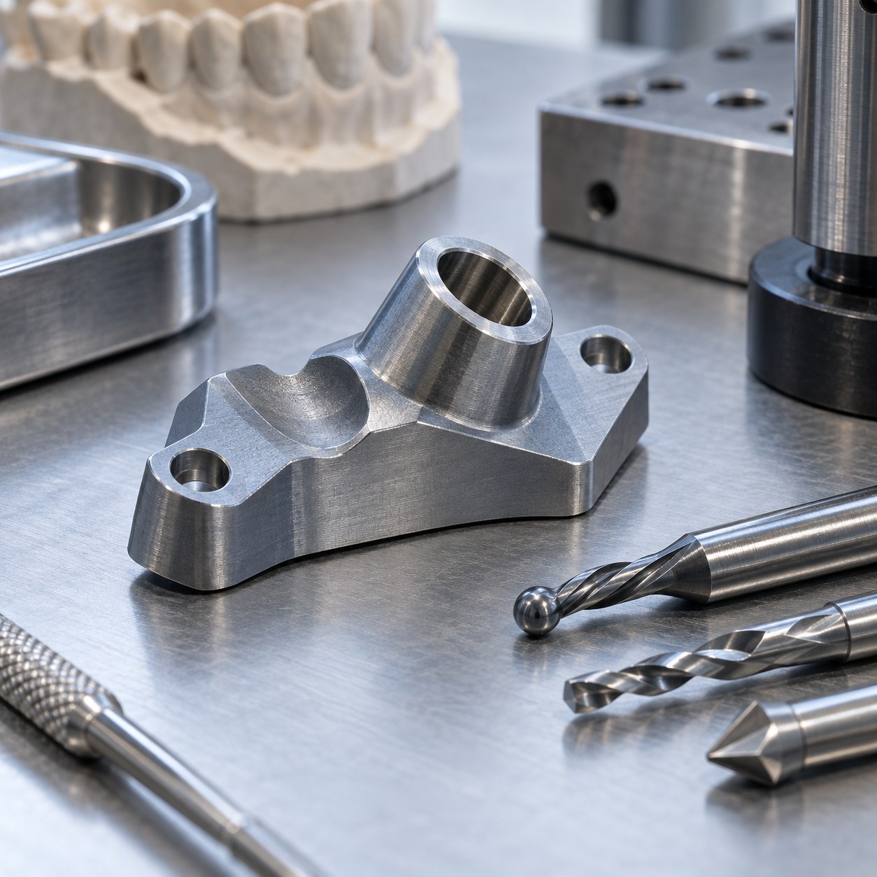
English: Ti-6Al-7Nb Drill Guide Tooling for Angled Sleeve Bore
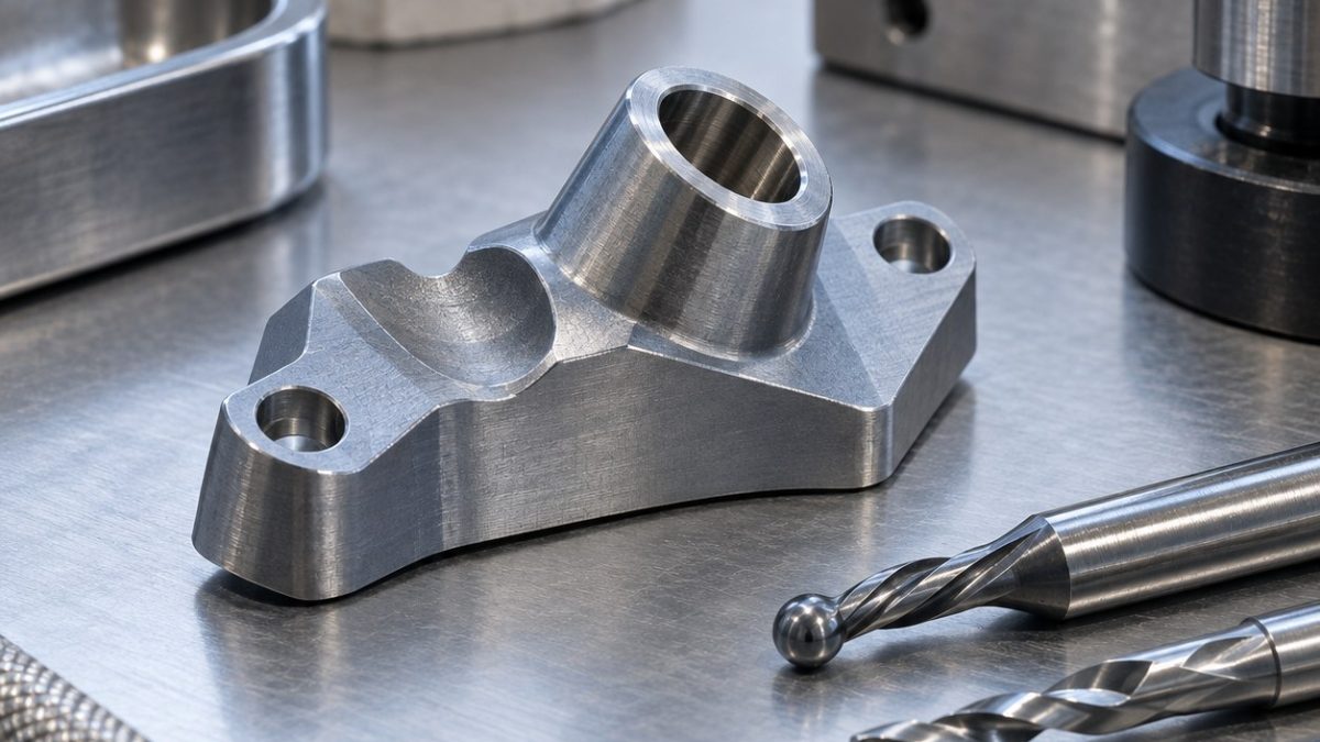
This hypothetical drill guide is controlled by the angular sleeve axis, not by the outside contour. The drawing uses a tooth saddle as a seating datum and an oblique bore that must remain normal to its own local plane. Any numerical tolerances are illustrative; a finished part still needs the clinical and regulatory validation defined for its use.
Reading the angled datum chain
Machine the underside and saddle while the stock remains broad, then locate that saddle on a conformal soft nest. Set the sine fixture from the drawing angle, spot and pilot the sleeve axis, and leave a small bore allowance for the final boring pass. Rough the outside only after the seating geometry is protected.
Tool map for the guide
| Feature | Tool | Decision |
|---|---|---|
| Tooth saddle | 4 mm 2-flute variable-helix TiAlN carbide ball end mill, short shrink holder | Shallow 3D finish follows the supporting surface; a long ball mill chatters. |
| Angled sleeve pilot | Carbide spot drill on a sine fixture | Creates a controlled start; drilling straight into the angled face wanders. |
| Sleeve bore | Indexable carbide drill followed by short fine boring bar | Boring corrects axis and size; a reamer cannot repair a displaced pilot. |
| Fixation holes | 2 mm coolant-through carbide drill, backing support | Peck only for evacuation; a dull HSS drill raises heat. |
| Edge break | 45° single-flute carbide chamfer mill | Small controlled chamfer avoids burrs; hand deburring changes seating. |
Heat, chips and finish
Titanium needs a cutting edge that keeps moving. Use a stable coolant strategy appropriate to the documented material and clean chips from the saddle before they rub. Blue discoloration, rising spindle load or a smeared bore wall means inspect the edge and fixture before changing only feed.
Inspection after release
Inspect the saddle before and after unclamping, then establish the sleeve axis with a probe or suitable optical system referenced to the local seating plane. Check bore size, fixation-hole position and all small chamfers under magnification. This geometry check does not certify a clinical workflow.
Practical tooling FAQ
Why bore after drilling?
The boring bar corrects size and axis at the final fixture datum.
Can a worn cutter be polished back?
Replace it; polishing changes geometry and does not restore edge integrity.
C77000 Nickel Silver EMI Frame CNC Tool Selection for Lid Rabbet and Spring Contact Slots · PPS-GF40 Battery Isolation Comb CNC Tool Selection for Thin Tines and Vent Slots