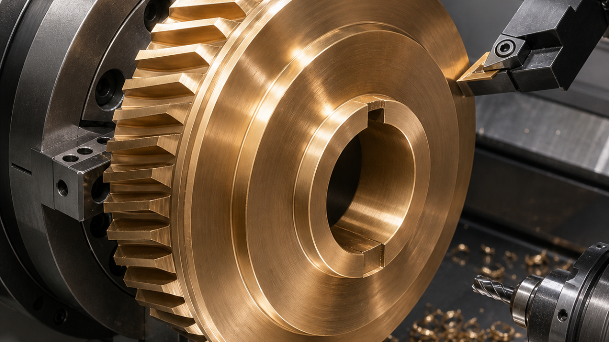
English: C95400 Aluminum Bronze Worm-Wheel Blank CNC Case: Bore Runout, Keyway and Burr Control
What the searcher needs to know: a C95400 aluminum-bronze worm-wheel blank should be finish-turned from its bore on a qualified expanding mandrel, with the tooth rim left as a controlled hobbing allowance and the keyway cut only after the bore-rim relationship is proven. This hypothetical case focuses on preventing built-up edge, cast-skin tool damage and keyway exit burrs.
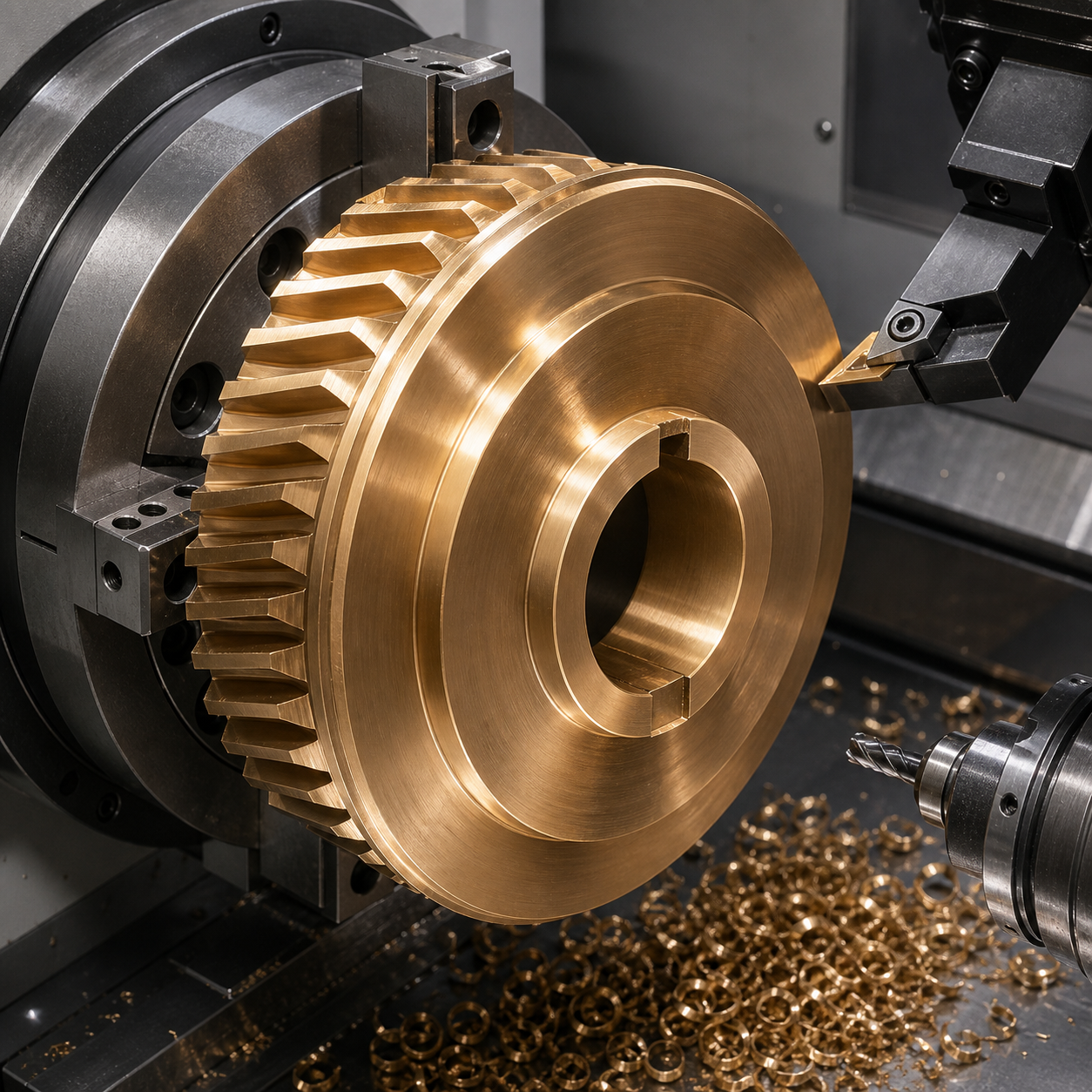
Drawing logic starts with the future gear mesh
The blank is Ø210 mm with a Ø65 H7 hub bore, 42 mm face width and 6 mm keyway. Datum A is the bore axis, B is one hub face and C is the keyway center plane. The pre-hob rim must run within 0.025 mm to A, B has 0.02 mm perpendicularity, and 2.2 mm radial hobbing stock must remain uniformly. The drawing separates final tooth data from blank dimensions so a machinist does not accidentally finish the rim to gear size.
Carbide grades matched to cast skin and clean bronze
The first cut uses a tough uncoated micrograin carbide insert with a positive geometry and a honed edge capable of crossing local cast hardness. Once skin is removed, a sharper polished positive insert controls built-up edge. A solid-carbide boring bar finishes the bore, while a three-flute carbide end mill roughs the keyway and a fresh two-flute tool finishes its width. Copious compatible coolant flushes dense chips from the hub; feed remains high enough to cut rather than rub.
From rough casting to bore-based finishing
At incoming inspection, ultrasonic or dye-compatible checks screen the critical hub-to-rim zone according to the material specification, and casting allowance is mapped at eight clock positions. First turning grips the rough rim in soft jaws, faces B, roughs the bore and leaves 0.5 mm on both functional diameters. The part is reversed on the machined face, the second face is brought parallel, and stress is allowed to equalize before final work.
A dual-taper expanding mandrel locates on the semi-finished bore with axial support near the hub, not beneath the flexible rim. Low clamping pressure is qualified with a roundness check. Bore finishing and rim turning then occur in the same spindle orientation: the boring pass establishes Ø65 H7, a light radial finish produces Ra 0.8 µm, and the outer rim is turned to preserve exactly 2.2 mm hobbing stock. Constant-surface-speed limits avoid overspeed at the rim.
Keyway strategy and chip control
The keyway is milled in a separate indexed setup that references A and B. A sacrificial bronze-backed exit insert supports the breakthrough side. Trochoidal roughing leaves 0.08 mm per wall; a climb-cut finish pass sizes the slot without dragging a built-up edge. Chips are flushed forward and vacuumed before probing. Edge break is a measured 0.15–0.25 mm, not an uncontrolled hand radius.
Tool-life risks and inspection handoff
Cast-skin inclusions can notch the first insert, while clean C95400 can weld to an overly blunt edge. Insert photographs, spindle-load change and bore-finish trend determine replacement. Final inspection uses a CMM or roundness system to build datum A, measure rim runout and B perpendicularity. An air gauge verifies H7 at three axial stations, a calibrated slot gauge checks keyway width, and a radial stock map accompanies the blank to hobbing. Surface roughness and burr height are recorded separately.
FAQ
Why finish a worm-wheel blank on an expanding mandrel?
It makes the functional bore the rotational datum, so rim runout and uniform hobbing stock are controlled directly.
Which carbide geometry suits C95400?
A tough positive insert removes variable cast skin; a sharper polished positive edge then limits built-up edge on clean material.
How much keyway burr is acceptable?
The drawing should define it. In this case a controlled 0.15–0.25 mm edge break replaces subjective hand deburring.
Related reading: bore and keyway datum planning and aluminum-bronze bore finishing.
中文: C95400铝青铜蜗轮坯加工:内孔跳动、键槽与毛刺控制
先给结论:C95400铝青铜蜗轮坯应以内孔为旋转基准,在经过验证的胀套芯轴上精车外缘,同时均匀保留滚齿余量;确认孔—轮缘关系后再加工键槽。这个假设案例专门处理铸皮伤刀、积屑瘤和键槽出口毛刺。
图纸服务于后续啮合
毛坯外径210 mm、轮毂孔Ø65 H7、齿宽42 mm、键槽6 mm。A为孔轴线,B为一侧轮毂端面,C为键槽中心面。滚齿前轮缘对A跳动0.025 mm,B对A垂直度0.02 mm,径向均匀保留2.2 mm滚齿余量。图纸必须把最终齿形数据与坯件尺寸分栏,防止误把轮缘加工到成品齿顶尺寸。
铸皮和净材使用不同刃口
首刀用韧性高、正前角、微钝化的无涂层细晶硬质合金刀片穿过局部硬铸皮;清除表层后改用锋利抛光正角刀片抑制积屑瘤。整体硬质合金镗杆精孔,三刃立铣刀开键槽,两刃新刀精宽。相容切削液大量前冲,进给不能低到只摩擦不切削。
两次粗基准与一次孔基准精加工
来料先在八个角向测余量,并按材料规范检查轮毂—轮缘关键区。首序软爪夹粗轮缘,车B、粗镗孔,两处各留0.5 mm;反装后把另一端面加工平行并释放应力。随后用双锥胀套以内孔定位,轴向支撑靠近轮毂而非柔性轮缘,低胀紧力通过圆度试验确认。
同一主轴姿态下精镗Ø65 H7并精车轮缘,孔面目标Ra 0.8 µm,径向余量严格保留2.2 mm;外圆采用受限恒线速,避免大直径超速。键槽另序以A、B定位,出口加牺牲背衬。摆线开粗每侧留0.08 mm,再顺铣精宽;边缘按0.15–0.25 mm定量倒钝。
刀寿命和滚齿交接检验
铸皮夹杂会让首刀产生沟槽磨损,净材则可能粘附在过钝刃口。用刀片照片、主轴负载变化和孔面趋势决定换刀。最终由三坐标或圆度仪建立A,测轮缘跳动和B垂直度;气动量仪在三个轴向位置测H7,槽规检键槽宽度,并把八方位滚齿余量图随件移交。粗糙度和毛刺高度分开记录。
常见问题
为何蜗轮坯要用胀套芯轴精加工?
因为功能内孔直接成为旋转基准,可直接控制轮缘跳动和滚齿余量均匀性。
C95400适合什么硬质合金刃形?
韧性正角刃先去铸皮,锋利抛光正角刃再加工净材。
键槽毛刺怎么验收?
图纸应量化;本案例规定0.15–0.25 mm边缘倒钝,不接受主观手工圆角。
Français: Ébauche de roue en bronze C95400 : faux-rond, alésage et clavette
Réponse recherchée : une ébauche de roue tangente en bronze C95400 se termine depuis son alésage sur un mandrin expansible qualifié, avec une surépaisseur de taillage uniforme; la rainure de clavette vient après validation du rapport alésage-jante. Ce cas hypothétique vise l’arête rapportée, la peau de fonderie et les bavures de sortie.
Le plan prépare l’engrènement
L’ébauche mesure Ø210 mm, avec alésage Ø65 H7, largeur 42 mm et rainure de 6 mm. A est l’axe, B une face de moyeu et C le plan médian de clavette. Le faux-rond avant taillage vaut 0,025 mm, B est perpendiculaire à 0,02 mm et 2,2 mm radiaux restent uniformément. Les données de denture sont séparées des dimensions d’ébauche.
Carbure selon l’état de surface
Une plaquette carbure positive tenace et légèrement préparée traverse la peau; une arête polie plus vive limite ensuite l’adhérence. Une barre carbure finit l’alésage, une fraise trois dents ébauche la rainure et une deux dents neuve calibre sa largeur. L’arrosage évacue les copeaux lourds et l’avance évite le frottement.
Montage et trajectoire
La surépaisseur est cartographiée à huit angles. Des mors doux tiennent d’abord la jante pour créer B et l’avant-trou avec 0,5 mm restant. Après retournement et relaxation, un mandrin bi-cône porte l’alésage, avec soutien près du moyeu. L’alésage H7 et la jante sont finis dans la même orientation pour conserver 2,2 mm avant taillage. La rainure est ensuite fraisée depuis A-B, avec martyr de sortie, ébauche trochoïdale à 0,08 mm par flanc et finition en avalant.
Usure et contrôle
Les inclusions entaillent la première plaquette; une arête trop émoussée favorise le collage. Photos, charge broche et tendance de rugosité commandent le changement. La MMT ou un appareil de circularité mesure le faux-rond et la perpendicularité; un calibre pneumatique contrôle H7 sur trois sections, une jauge vérifie la clavette, et la carte de surépaisseur accompagne la pièce au taillage.
FAQ
Pourquoi un mandrin expansible ?
Il transforme l’alésage fonctionnel en axe de rotation et maîtrise directement la jante.
Quelle géométrie carbure pour le C95400 ?
Une arête positive tenace pour la peau, puis une arête positive polie pour le métal propre.
Comment spécifier la bavure de clavette ?
Par une valeur mesurable; ici, un cassage d’arête de 0,15 à 0,25 mm.
Voir la construction des références alésage-clavette et la finition d’alésage en bronze aluminium.
Русский: Заготовка червячного колеса C95400: биение и шпонка
Краткий ответ: заготовку червячного колеса C95400 чистят от функционального отверстия на проверенной разжимной оправке, равномерно оставляя припуск под зубонарезание. Шпоночный паз выполняют после подтверждения связи отверстия с ободом. Пример гипотетический.
Требования под будущие зубья
Диаметр 210 мм, отверстие Ø65 H7, ширина 42 мм, паз 6 мм. A — ось отверстия, B — торец ступицы, C — средняя плоскость паза. Биение обода до нарезания 0,025 мм, перпендикулярность B 0,02 мм, радиальный припуск 2,2 мм. Размеры заготовки отделены от окончательных параметров зубьев.
Твёрдый сплав для корки и чистого металла
Литейную корку проходит прочная позитивная мелкозернистая пластина с небольшой подготовкой кромки; затем острая полированная пластина уменьшает нарост. Твердосплавная расточная оправка заканчивает отверстие, трёхзубая фреза черновит паз, новая двухзубая калибрует ширину. Поток совместимой жидкости выводит тяжёлую стружку.
Маршрут по оси отверстия
Припуск измеряют в восьми угловых точках. Сначала мягкие кулачки держат грубый обод, создавая B и черновое отверстие с припуском 0,5 мм. После переворота и выдержки разжимная двухконусная оправка базирует отверстие, опирая ступицу. Ø65 H7 и обод заканчивают при одной ориентации, сохраняя 2,2 мм. Паз фрезеруют от A-B с выходной подкладкой: трохоидально оставляют 0,08 мм на сторону и чистят попутно.
Ресурс и приёмка
Включения вызывают канавочный износ, а тупая кромка — налипание. Замену определяют по фото пластины, нагрузке и качеству отверстия. КИМ или кругломер контролирует биение и торец; пневмокалибр измеряет H7 в трёх сечениях, паз проверяет калибр. Карта припуска в восьми положениях передаётся на зубонарезание.
Вопросы
Зачем разжимная оправка?
Она превращает рабочее отверстие в ось вращения и напрямую задаёт биение обода.
Какая геометрия нужна C95400?
Прочная позитивная для корки, затем острая полированная для чистого металла.
Как задать заусенец паза?
Измеримой фаской; здесь 0,15–0,25 мм вместо произвольной ручной зачистки.
Сравните с базированием отверстия и шпонки и расточкой алюминиевой бронзы.


