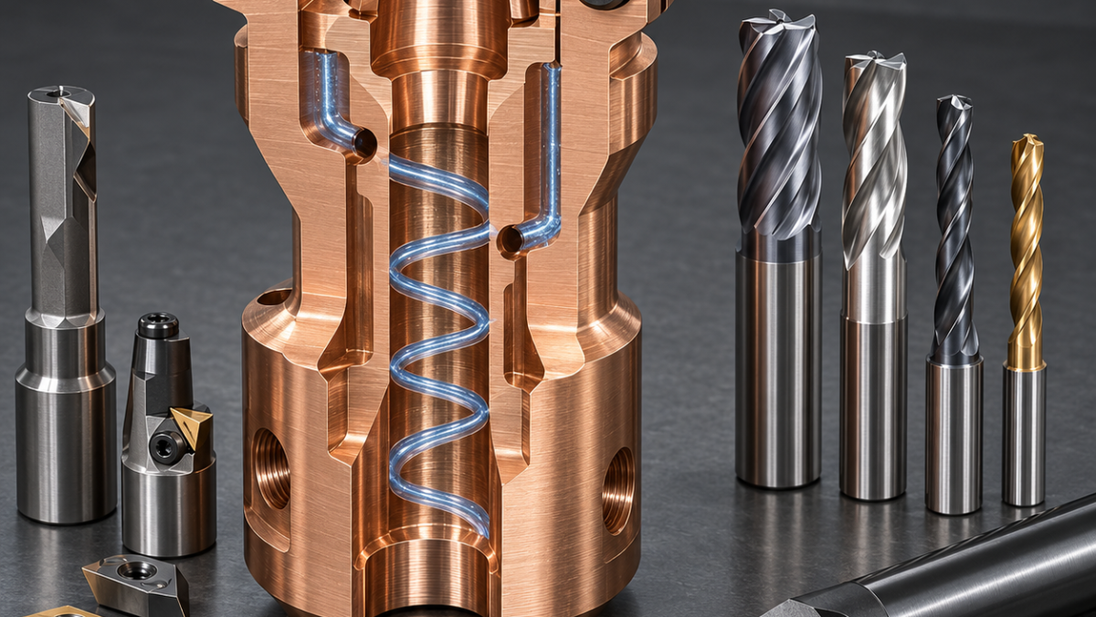
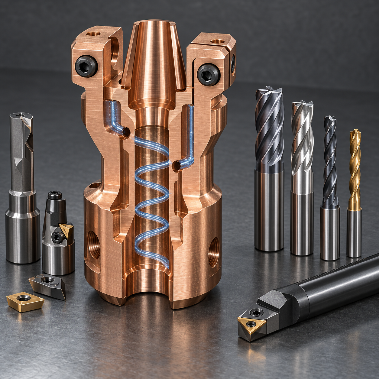
English: C17510 Electrode Holder Tooling for a Taper Socket and Helical Cooling Passage
The search problem is how to machine a C17510 electrode holder whose electrode taper must transfer heat while a helical passage approaches the socket wall. The drawing couples taper contact, minimum coolant ligament and clamp-slot spring, so the tool plan must protect all three rather than maximize metal removal.
Let the contact taper own the datum chain
Turn the mounting pilot and reference face with a polished positive CCGT insert, then rough the socket with a short 10 mm boring bar. Semifinish the taper by circular interpolation with an 8 mm three-flute uncoated polished carbide mill; finish it with a single-point fine boring head referenced to the pilot. A form reamer is rejected because it follows runout and cannot correct taper position.
Feature-to-tool decisions for the electrode holder
| Drawing feature | Carbide tool and holder | Selection logic / rejected alternative |
|---|---|---|
| Pilot and reference face | Polished positive CCGT, 0.2 mm nose radius, rigid holder | Low cutting force avoids smearing; a honed steel-grade insert rubs. |
| Electrode taper | 8 mm 3-flute polished mill for semifinish; fine boring head for finish | Corrects axis and contact; a form reamer follows runout. |
| Helical coolant channel | 5 mm 2-flute polished radius mill, hydraulic chuck | Large gullets clear copper curls; four flutes pack chips. |
| Cross ports | 3 mm through-coolant micro-grain carbide drill, 8xD | Positive evacuation protects the thin ligament; pecking dry work-hardens the wall. |
| Split clamp and intersections | 1.2 mm carbide slitting saw plus reverse chamfer cutter | Balanced slot force and controlled burr removal; a long end mill spreads the ears. |
Create the cooling path before releasing the clamp
Fixture the solid body in a collet from the pilot. Mill the external helical channel with a 5 mm two-flute polished radius end mill, close it later with the drawing-specified sleeve process, and drill transverse ports with 3 mm through-coolant carbide drills. Cut the split slot last using a 1.2 mm fine-pitch carbide slitting saw supported on both ears; a long end mill would push the ears apart.
Control copper-alloy smearing at every intersection
Use high-flow emulsion and generous flute space because C17510 forms adhesive curls. Back-chamfer each port intersection with a small reverse cutter rather than a hand wire. Verify taper contact with bluing and a master, map wall thickness ultrasonically around the helix, pressure-test the circuit, then measure clamp gap free and at drawing load. Tool life ends at rising burr height, torque or contact-band drift.
Related tooling comparisons: tellurium-copper RF feedthrough tooling; OFE copper beam-mask tooling.
Electrode-holder tooling FAQ
Coated or uncoated? Polished uncoated carbide limits built-up edge; a thin DLC option needs coolant compatibility proof. Why finish the slot last? The closed ring stabilizes taper boring and passage machining. Can the taper be reamed? Only for size after position is already correct; it cannot recover axis error.


