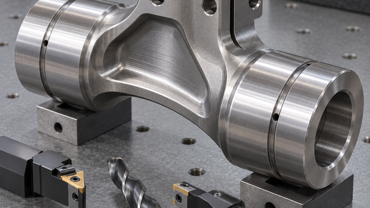
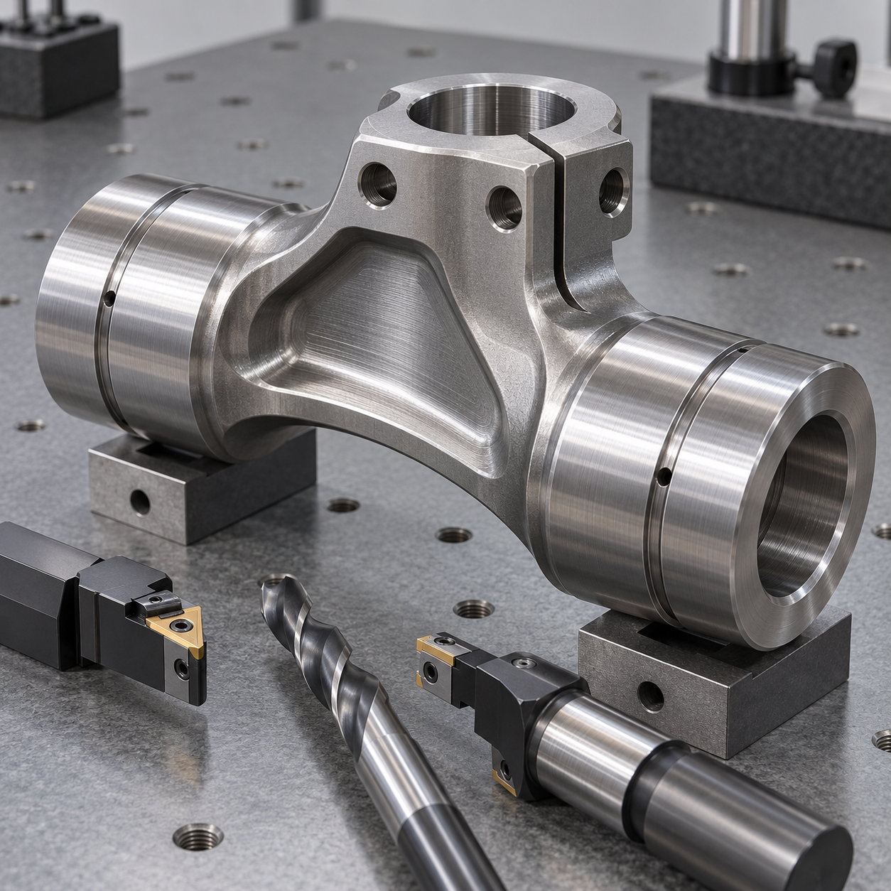
English: 300M Rotor Trunnion Tooling for Opposed Journals, Clamp Slot and Grease Grooves
The drawing is controlled by what moves after heat treatment. Two bearing journals share an axis across a relieved center web, while the split clamp must close without pulling either journal oval. The tooling plan reserves grind stock where hardness demands it and finishes flexible features only after the main axis is proven.
Build a heat-treatment error budget around the journal axis
Normalize and probe the forging, then face and rough both journal envelopes from a common center. An indexable high-feed carbide mill opens the central relief in alternating layers; a 16 mm variable-helix end mill blends the web. Journals are semifinished with a tough CVD turning grade, leaving equal cylindrical grind allowance and protected centers for post-heat-treatment location.
Tool decisions from forging to hardened trunnion
| Drawing feature | Carbide tool and holder | Selection logic / rejected alternative |
|---|---|---|
| Forging datum and ends | 80 mm indexable face mill, tough CVD inserts; carbide center drill | Creates balanced centers; gripping one raw end biases stock. |
| Central relief web | High-feed carbide rougher then 16 mm, 5-flute variable-helix end mill | Alternating layers balance stress; a deep full-width slot bends the web. |
| Opposed journals | CVD semifinish turning insert, then vitrified CBN grinding wheel | Stock survives heat treatment; hard turning alone risks lobing and scale damage. |
| Clamp slit and bolt bores | 1.2 mm PVD carbide saw; 8 mm AlTiN interpolator; carbide reamer | Saw limits force and reamer controls size; broaching the open slit can wedge it. |
| Grease grooves and intersections | 2 mm full-radius carbide groover plus reverse chamfer tool | Controlled radius and internal edge; hand deburring cannot be verified. |
Rough symmetrically before the clamp is opened
After hardening and tempering, locate between restored centers and cylindrical-grind the opposed journals. Mill the clamp slit with a 1.2 mm PVD-coated carbide slitting saw using a full-length support mandrel, then interpolate the cross-bolt bores with an 8 mm AlTiN end mill and finish with a carbide reamer. Cutting the slit before hardening is rejected because opening movement becomes unpredictable during quench.
Release the split without sacrificing roundness
Finish grease grooves with a 2 mm full-radius carbide groove tool and break the feed intersections with a reverse chamfer cutter. Inspect coaxiality between centers, then repeat roundness with the clamp bolt loose and at drawing torque. Magnetic-particle inspection follows all grinding; a Barkhausen or burn check is used when the hypothetical quality plan requires it.
Related tooling comparisons: landing-gear axle tooling; fork and pin-bore tooling.
300M trunnion tooling FAQ
Why grind rather than hard turn the journals? The roundness and heat-treatment scale allowance favor a controlled abrasive finish. Why ream after interpolation? Interpolation corrects position; reaming stabilizes bore size. When is the saw replaced? When slot width, side burr or spindle load trends leave the qualified window.


