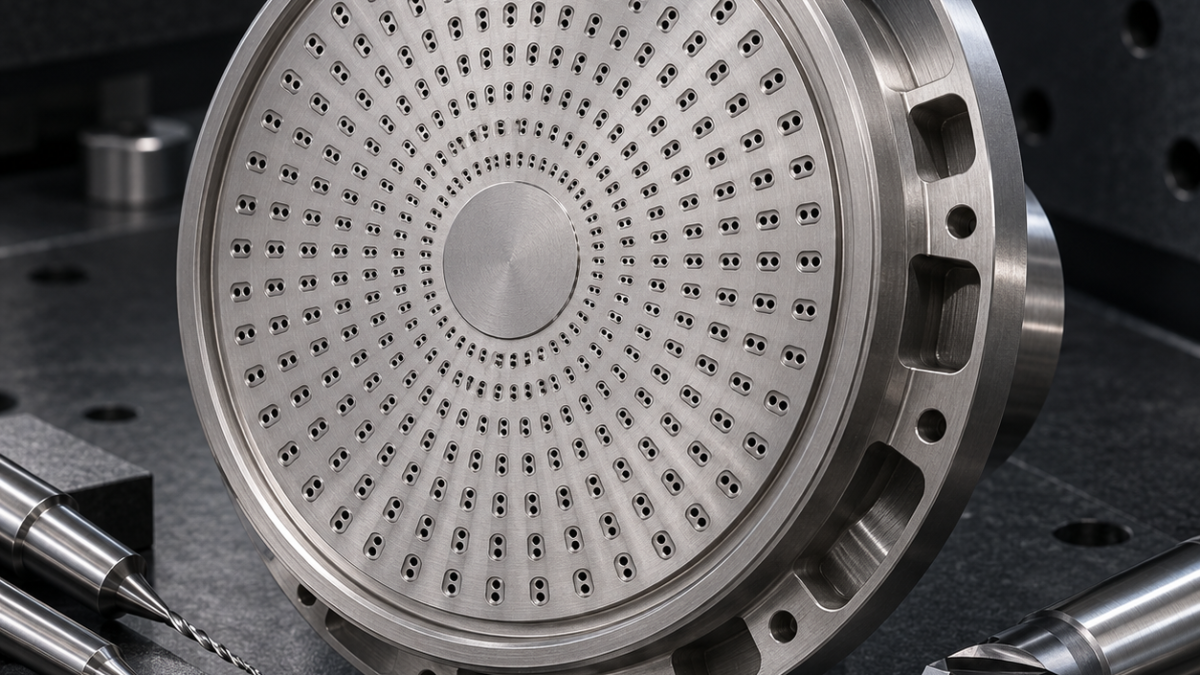
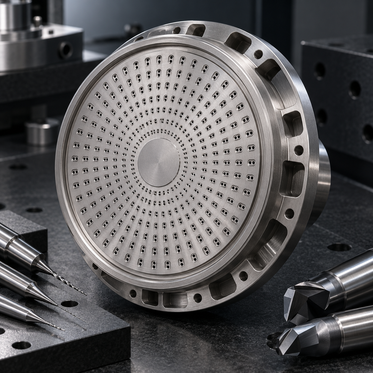
English: C103 Niobium Injector Faceplate Tooling for Coaxial Micro Orifices and Seal Lip
The long-tail problem is not simply drilling many small holes. Each coaxial pair meters a hypothetical flow stream, so diameter, overlap, burr volume and local plate thickness act together. The drawing groups orifices by flow family; the process must keep those families traceable without claiming real engine performance.
Use flow families to control the hole array
Vacuum-compatible soft jaws locate the forged blank on its outer pilot. Face the chamber side with a polished uncoated CCGT insert, then finish the annular seal lip with a separate sharp wiper at constant radius. Rough radial feed pockets from the rear using a 6 mm three-flute polished carbide end mill while the front face is still supported.
Feature-to-tool decisions for ductile C103 niobium
| Drawing feature | Carbide tool and holder | Selection logic / rejected alternative |
|---|---|---|
| Chamber face and seal lip | Polished uncoated CCGT plus sharp wiper, 0.2 mm radius, rigid holder | Shears ductile niobium; a honed coated insert smears the lip. |
| Rear feed pockets | 6 mm 3-flute polished carbide radius end mill, hydraulic chuck | Large flute space clears stringy chips; five flutes pack material. |
| 1.2 mm rear orifices | Uncoated micro-grain carbide drill, polished flute, 6xD | Sharp evacuation; TiAlN warmth promotes adhesion. |
| 0.6 mm front orifices | Uncoated carbide micro drill in air-bearing spindle, minimum projection | Runout control protects diameter; long holders break the drill. |
| Micro edge break | 0.4 mm diamond-coated lapping pin or qualified micro abrasive flow | Controls smear without enlarging the hole; hand wires ovalize it. |
Create the seal lip before the plate becomes fragile
Spot each pair with a 120-degree carbide micro spotter just deep enough to break the skin. Drill the larger rear orifice first using a 1.2 mm polished-flute uncoated carbide drill, then the 0.6 mm front orifice from the seal side using a precision air-bearing spindle. TiAlN is rejected because niobium can adhere to a warm coated edge; sharp uncoated geometry and continuous chip withdrawal reduce smearing.
Drill paired orifices without smearing
Use optical focus and pin metrology for diameter, CT or calibrated borescope for pair overlap, and filtered flow only as a comparative acceptance signal. Map every result to the programmed flow family; do not average a blocked hole into the group. Tool life ends when thrust, entry lip height or diameter drift changes, even if the drill remains intact.
Related tooling comparisons: niobium seal-land tooling; micro-orifice inspection.
Niobium faceplate tooling FAQ
Why drill from two sides? It shortens each fragile tool reach and controls the mixing overlap. Can EDM replace drilling? It changes recast and edge condition and requires its own qualification. How is the seal protected? Dedicated jaws, noncontact cleaning and final inspection after all deburring.
For the drill, holder, exit-support and burr-control decision behind this feature, use the Micro-hole decision hub.


