This is a realistic hypothetical process-planning case, not a customer project or confidential drawing.
English: PEEK Bearing Cage CNC Case: Thin Windows, Thermal Control and Burr-Free Finishing
Search intent and drawing interpretation
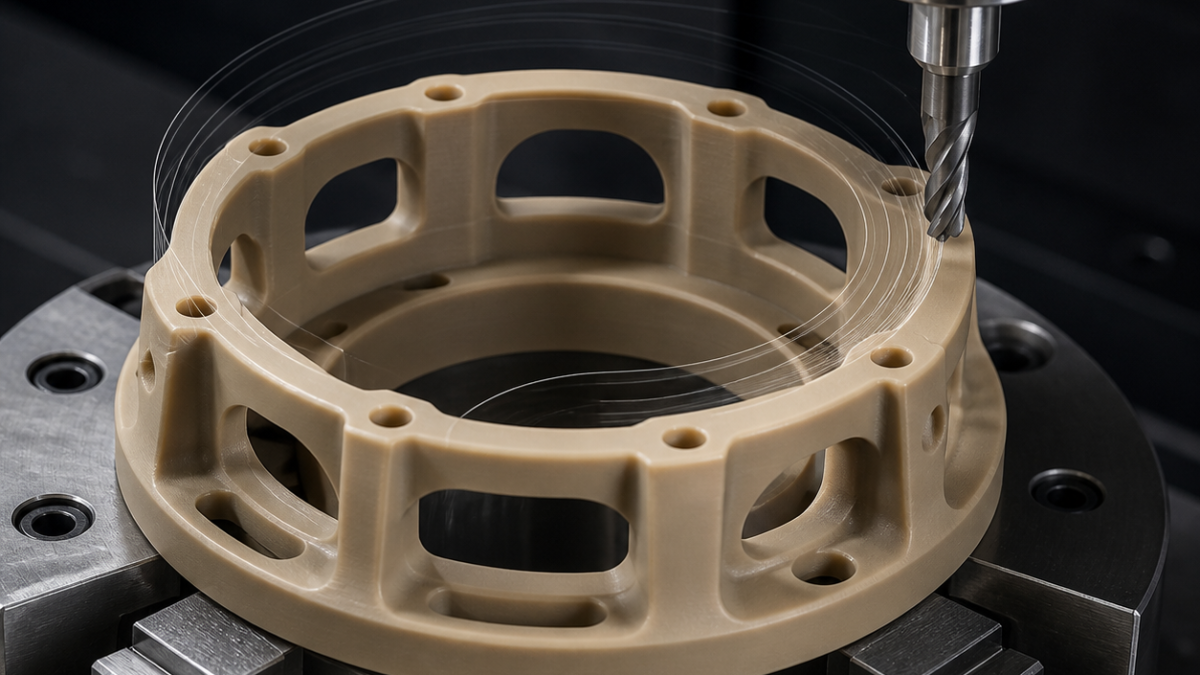
For a PEEK bearing cage with thin windows, the reliable answer is to use very sharp polished carbide tools, low clamping force, staged window opening and temperature-aware inspection. Read the drawing by linking window width, cage roundness, pocket radii and edge-break notes to one datum scheme; do not treat each tolerance independently.
- Primary datum: finished pilot bore or a protected annular face
- Critical relation: window position to pitch circle and cage axis
- Check whether edge breaks are controlled dimensions or only burr-removal notes
Carbide tool selection
Use polished, razor-sharp uncoated carbide geometry made for non-ferrous materials. A short 2-flute end mill clears PEEK chips; a smaller relieved-neck cutter finishes corner radii; a dedicated sharp chamfer mill controls edge breaks. Avoid worn tools because rubbing heats and smears the polymer.
Fixture and process plan
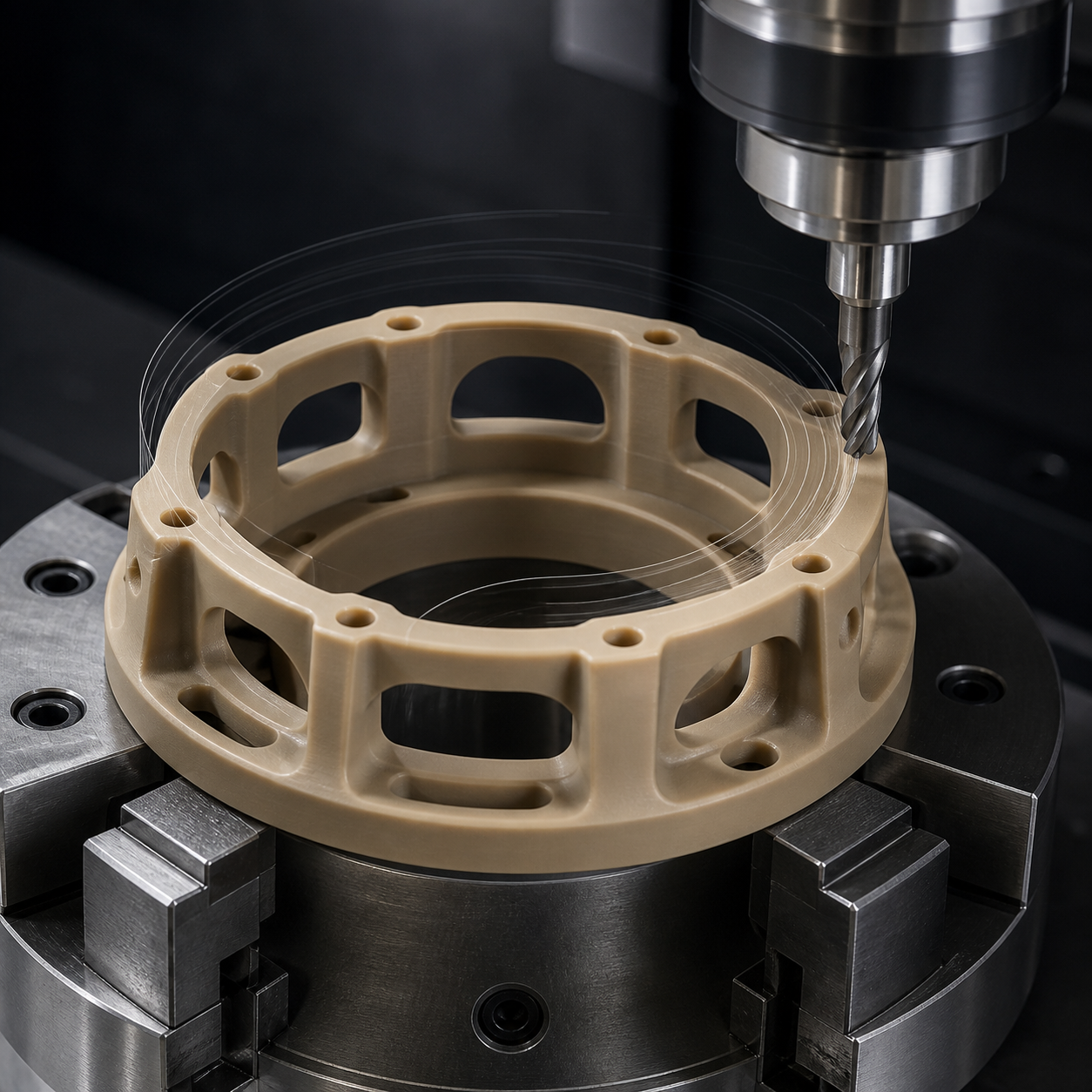
Turn the datum face and bore first in soft jaws, then support the ring on a close-fitting expanding mandrel or contoured nest. Rough alternating windows so material remains balanced. Leave uniform radial and floor stock, allow the part to return near room temperature, and finish in a second low-force setup.
- Roughing: high positive rake, moderate chip load, no dwelling
- Finishing: climb mill with one consistent light radial pass
- Keep vacuum extraction or dry air aimed away from recutting chips
Toolpaths, tolerances and surface finish
Use helical entry or pre-opened access rather than plunging a small cutter into solid PEEK. Limit arc engagement at the thin ribs, blend leads outside the finished wall, and avoid repeated spring passes that only add heat. Inspect size at the drawing reference temperature; roundness and window profile matter more than a glossy but distorted surface.
Material risks, chips and tool life
PEEK expands more than metal, can recover after unclamping and produces light stringy chips. Heat, chip recutting and a dull edge cause fuzz or smeared corners. Tool-life limits should therefore be based on burr growth and dimensional drift, not catastrophic wear.
Inspection plan
Verify bore size and roundness with a low-force bore gauge, window position optically or on a CMM, wall thickness at several clock positions, and free-state flatness after thermal stabilization. Record actual part temperature for any tight dimensional decision.
PEEK bearing cage machining FAQ
How do you prevent burrs when milling PEEK windows?
Use a truly sharp polished cutter, support the exit edge, maintain chip thickness and make a dedicated light finishing pass.
Should coolant be used on PEEK?
Dry air or controlled coolant can work; the process must avoid heat buildup, swelling concerns and chip recutting.
Why does the bore change after unclamping?
Clamp stress and machining heat can temporarily distort PEEK, so free-state thermal stabilization is essential.