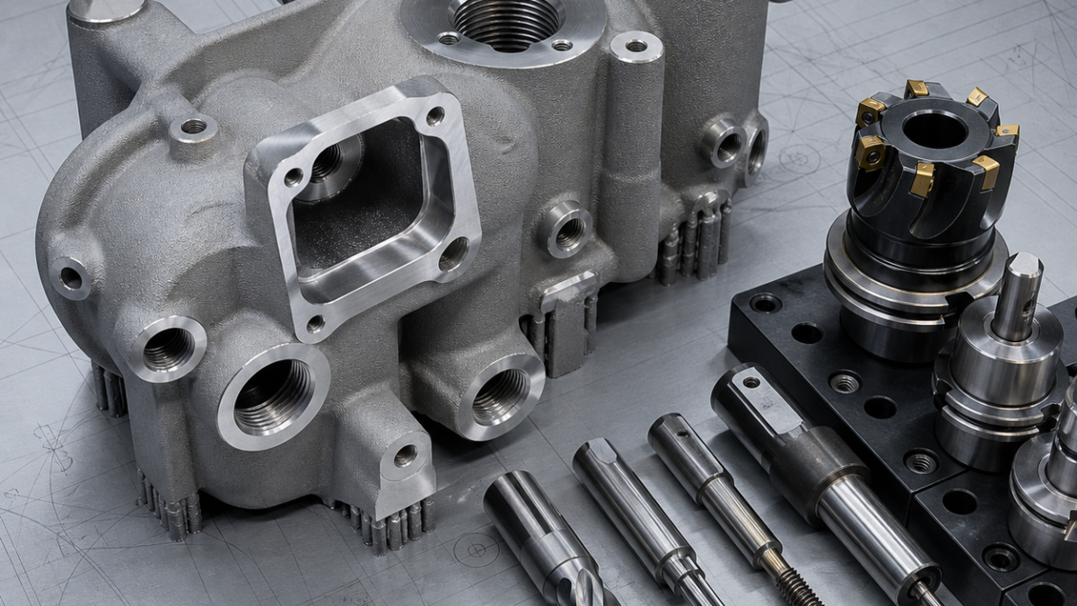
This is a realistic hypothetical process-planning example, not a claim about a specific customer drawing or production result.
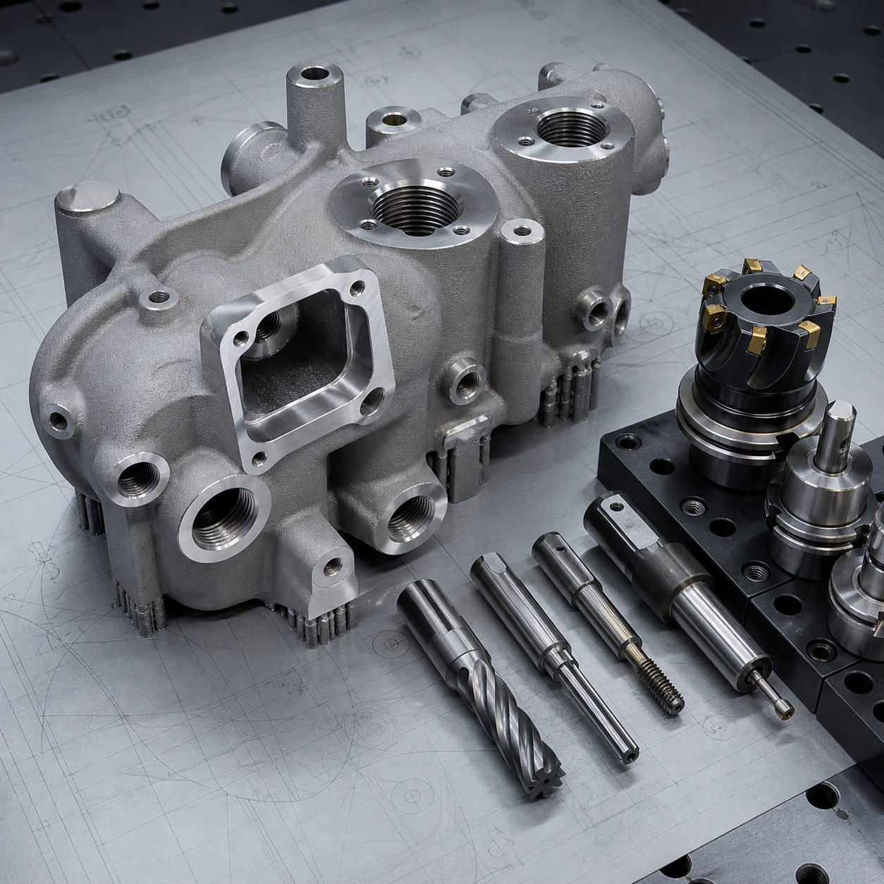
Related: Read the related CNC tooling case.
English: Additively Manufactured AlSi10Mg Hydraulic Manifold CNC Case: Datum Bosses, Seal Faces and Port Finishing
This hypothetical AlSi10Mg manifold is printed near net shape with sacrificial supports, dedicated datum bosses, curved internal passages and machining allowance on seal faces and ports. The CNC plan must reconcile the as-built scan with the nominal model before any critical stock is removed.
Feature and datum interpretation
Use three printed pads to create datum A, a reamed transfer hole for B and a second boss for clocking C. Compare the scan to nominal and verify that every sealing face and threaded port has cleanup stock. Internal passages should be treated as inspection features even when they are not directly machined.
Carbide tool selection
Use a positive-rake face mill or PCD-compatible cutter for sealing pads, sharp carbide end mills for support stubs, carbide drills and reamers for datum holes, and thread mills for ports. A back-deburring tool reaches break-through edges; low cutting force helps avoid opening subsurface porosity.
Fixture and process sequence
Remove only supports that obstruct the first fixture, then skim datum bosses and probe the full part. Finish primary seal faces and transfer holes in the most rigid orientation. Refixture through the recovered datums for ports, thread milling and controlled edge breaks, leaving nonfunctional additive surfaces untouched.
Tolerance, surface and tool-life risks
Printed variation, trapped powder, porosity and residual stress can create leaks or datum shift. Use staged probing, filtered extraction and conservative breakthrough moves. Pressure-test requirements come from the drawing or process specification; do not infer acceptance from visual finish alone. Verify thread gauges, face flatness, port position and internal burr condition.
FAQ
Why recover datums before finishing?
Because the functional geometry must be related to the actual part, not an assumed nominal center.
Why inspect after unclamping?
Clamping can temporarily hide distortion or runout.


