This is a realistic hypothetical process-planning example, not a claim about a specific customer drawing or production result.
Related: Compare bore-datum planning in the cast-iron bearing housing case and coaxial inspection in the hinge fitting case.
English: reading the split bearing-cap drawing
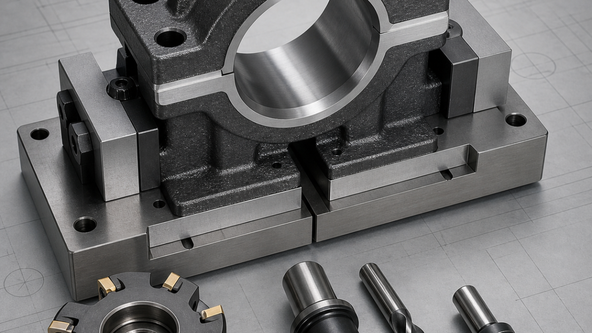
This hypothetical ductile iron cap is not a stand-alone half-round part. Its joint face, dowel locations, bolt seats and bearing bore become functional only when assembled to the matching lower housing. The process plan must therefore distinguish dimensions machined on the cap alone from the final bore and alignment requirements verified as a pair.
Drawing datums and matched identity
Create datum A on the joint face, datum B on one side locator and datum C from the dowel pattern. Keep cap and lower housing as a controlled pair through final boring. Confirm the specified joint-face gap, bolt preload state and whether bore size is measured assembled, because each condition changes the result.
Face mill, drill and boring package
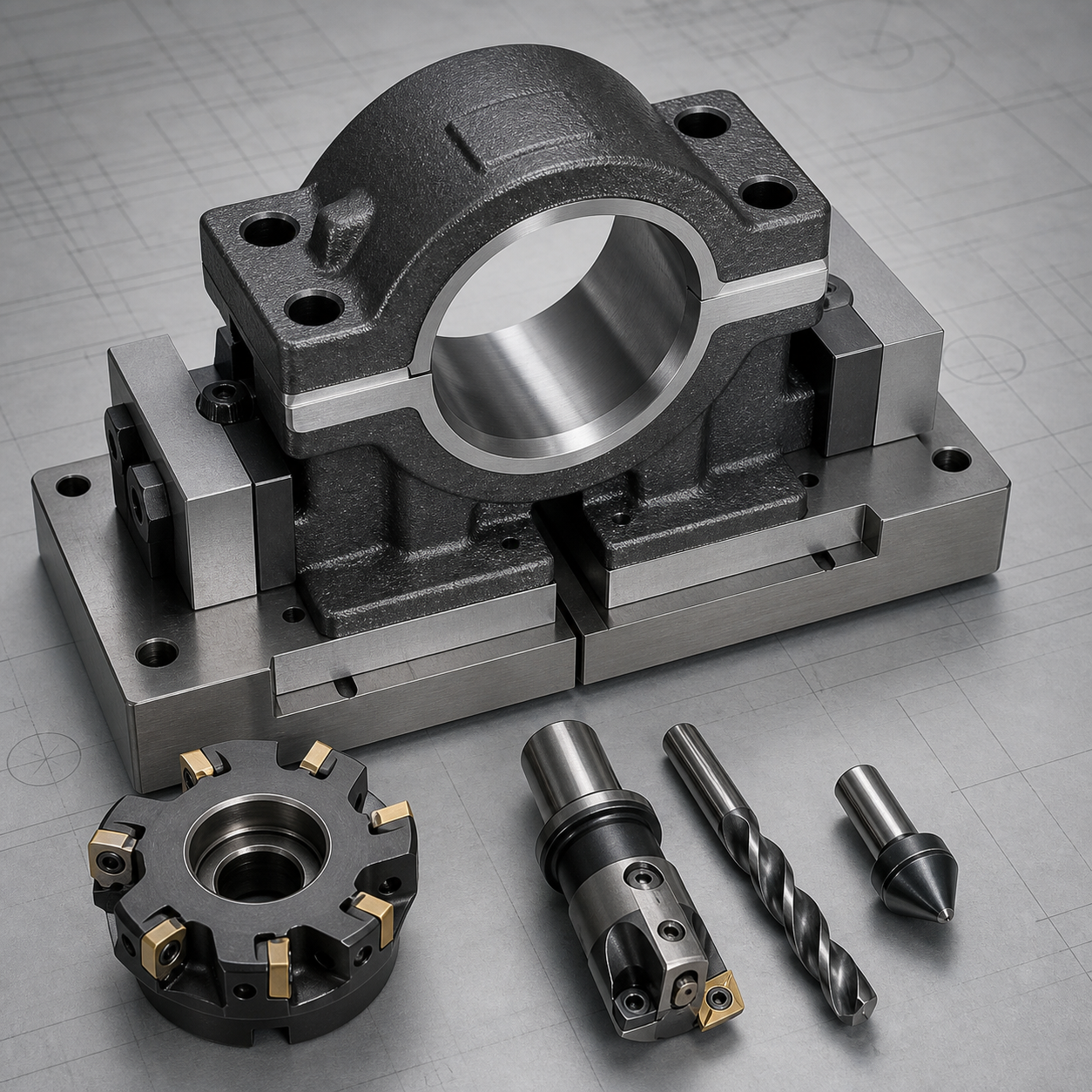
Use a close-pitch carbide face mill suited to ductile iron for the joint face, indexable or solid-carbide drills for bolt holes, and a piloted carbide reamer for dowels. A rigid fine-boring head or line-boring bar finishes the assembled bore; a light chamfer tool protects the split edges without rounding the bearing seat.
Fixture and sequence
Machine the joint face and bolt seats in a stable three-point fixture. Drill and finish dowel holes from the same datum set, then assemble the cap to its mate using production-equivalent bolts and tightening sequence. Support the pair near the bore, rough-bore with balanced stock, allow stress to settle, and finish in one uninterrupted pass.
Tolerance, graphite and tool-life risks
Casting skin and interrupted entry can chip inserts, while graphite dust accelerates wear and contaminates slides. Use effective extraction and inspect the raw allowance before committing the finish edge. Check bore size, roundness and axis location in the specified clamped state, then release and recheck the joint to reveal preload distortion.
FAQ
Why bore the cap and housing together?
The assembled joint, dowels and bolt preload establish the actual circular bearing seat.
Can the dowel holes be located after boring?
Usually the dowels should establish the repeatable pair before final boring, unless the drawing defines another datum strategy.


