English: Carbide End Mill Cutting Parameters by Material, Geometry and Engagement
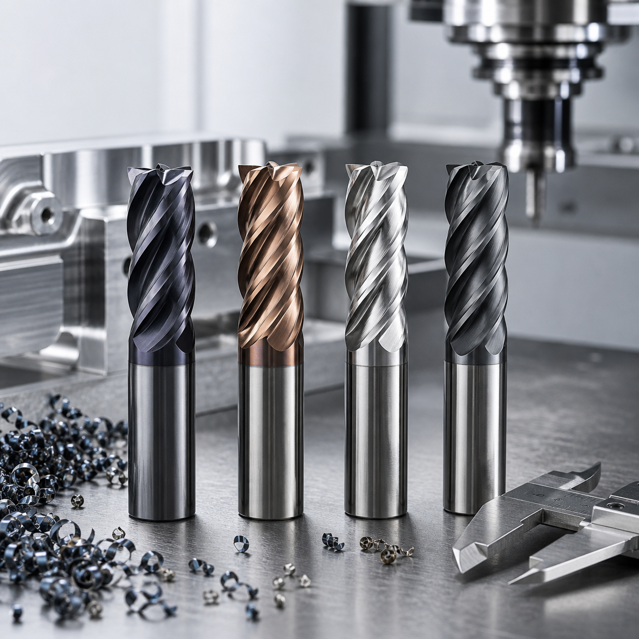
A usable carbide end mill cutting-parameter plan starts with the work material and the drawing feature, not a copied speed-and-feed number. Select geometry and coating first, calculate spindle speed and feed from the tool maker’s starting surface speed and chip load, then correct for radial chip thinning, tool overhang, entry style and machine limits. The values below are decision ranges for a hypothetical setup, not universal production guarantees.
Build the parameter sheet from the drawing
Record alloy and condition, tool diameter, effective flute length, corner radius, holder, measured runout, radial engagement ae, axial depth ap and whether the cut is a slot, wall, pocket or finish pass. A 10 mm five-flute steel rougher at 10% radial engagement does not share the same feed logic as a three-flute aluminum slotter at 100%. For thin walls or long reach, stiffness can set the ceiling before carbide strength does.
| Material and feature | Carbide end mill decision | Parameter starting logic | Reject when |
|---|---|---|---|
| 6061 pocket, open chip space | Ø10, 3-flute, polished high-positive edge, uncoated/ZrN, hydraulic holder | High surface speed; start chip load from maker data; ae 8–15% for adaptive roughing | AlTiN on a sharp aluminum edge if built-up edge begins |
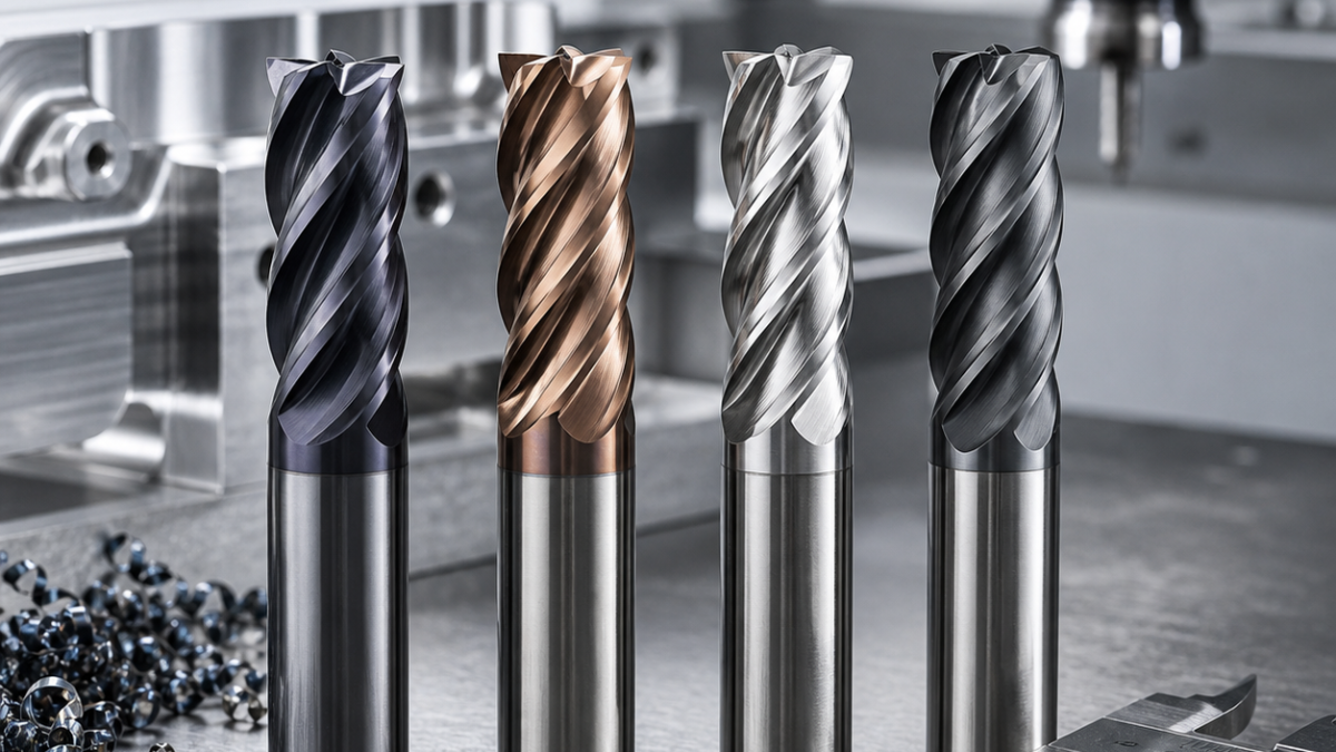
| 304 stainless side wall | Ø10, 5-flute, unequal helix, tough submicron grade, AlTiN/AlCrN | Moderate speed; maintain feed through corners; ae 6–10% and controlled ap | Dwell, feathering feed, or a long weak holder |
| Ti-6Al-4V deep pocket | Ø8, 4-flute, sharp reinforced edge, TiAlN-family PVD, through-tool coolant | Low surface speed; constant engagement; limit heat with ae 5–8% | Full-width burying or recutting hot chips |
| Hardened steel finish | Ø6 ball/radius, 4–6 flute, fine-grain carbide, AlTiN/AlCrN | Small stock, stable contact, calculate effective diameter on 3D surface | Using nominal ball diameter for speed at a shallow contact point |
Calculate, then apply four corrections
Use n = 1000Vc/(πD) and feed = n × z × fz. Next, increase programmed fz only where low radial engagement makes actual chip thickness smaller; reduce it again if runout gives one flute most of the load. Derate for overhang beyond roughly 3×D, weak workholding or interrupted entry. Finally cap the result by spindle speed, power, acceleration and controller look-ahead. Do not hide an acceleration problem by globally lowering chip load: smooth the toolpath and protect corner feed instead.
Roughing, semifinishing and finishing need separate tools
A radius rougher carries stock and heat; a separate semifinisher restores a predictable wall and leaves uniform stock; the sharp finisher controls size and surface. Sharing one worn tool across all three stages couples roughing wear to final tolerance. On a bore or sealing wall, use a short holder and verify flute runout before applying diameter wear compensation. Reject a longer cutter merely because it reaches: a reduced-neck tool or staged setup often gives lower bending compliance.
Read evidence before changing the number
Stable chips should have consistent thickness and color for the material. Rising spindle load with shiny rubbed chips suggests too little real chip thickness or a worn edge; chatter marks at a repeatable pitch point to dynamics or runout; corner chipping after every entry points to engagement and path shape. Measure finished size, wall taper and Ra, record tool life by actual cutting time, and change one variable at a time. Tool-life decisions should use flank wear, notch wear, edge chipping, load trend and surface trend together.
Related: feed-per-tooth calculation guide; tool-holder runout diagnosis; carbide edge-preparation guide.
A spindle-limit calculation that can be audited
The following numbers are a hypothetical arithmetic check, not recommended cutting data for a particular alloy. Assume a Ø10 mm, four-flute end mill and manufacturer-approved starting inputs of Vc = 120 m/min and fz = 0.040 mm/tooth for the actual engagement. The calculated speed is approximately 3,820 rpm and feed is 611 mm/min. If the approved spindle/assembly limit is 3,000 rpm, recalculate feed to 480 mm/min; retaining 611 would raise programmed fz to approximately 0.051 mm/tooth.
| Record on the setup sheet | Calculated condition | At the 3,000 rpm limit |
|---|---|---|
| Spindle speed | 3,820 rpm | 3,000 rpm |
| Programmed feed per tooth | 0.040 mm | 0.040 mm |
| Linear feed | 611 mm/min | 480 mm/min |
| Actual surface speed | 120 m/min | 94.2 m/min |
Before release, record whether chip-thinning correction is already included in the selected fz. This calculation adds none. Check the worst corner engagement, approach move and machine feed mode separately; a straight-line calculation does not validate an internal circular path. Retain the same tool assembly and fixture for the first comparison, then inspect dimensional drift, wall taper, burrs and edge wear before accepting a higher removal rate.
The Ti-6Al-4V bracket support sequence shows why a correct feed calculation still needs a stiffness check. The Zr 702 narrow seal-groove case adds a different limit: a small dedicated finishing tool and measured residual stock, not the rougher’s feed, control the functional groove.
What if a lower speed gives a worse finish?
Do not assume the arithmetic is wrong or immediately raise feed. Confirm that the capped speed remains inside the tool supplier’s usable range and inspect adhesion, runout and chip evacuation. A mathematically consistent setting can still be unsuitable for that material or operation.
Cutting-parameter questions
Should catalog data be copied directly? No. It is a controlled starting point for the stated tool, holder and material condition. Which parameter should be corrected first? Confirm runout and actual engagement before changing chip load. Why can a lower feed shorten life? If chip thickness falls below the edge hone, the tool rubs, heats and work-hardens the surface.
Geometry follow-up: Use the chipbreaker roughing-end-mill guide when stock removal and chip width govern the tool, the wiper-geometry guide when a broad finishing land must control floor finish, and the drill-mill guide only for spotting, chamfering and light interpolation rather than heavy pocket roughing.