English: Drawing Review and Manufacturing Challenge
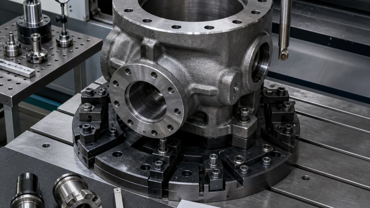
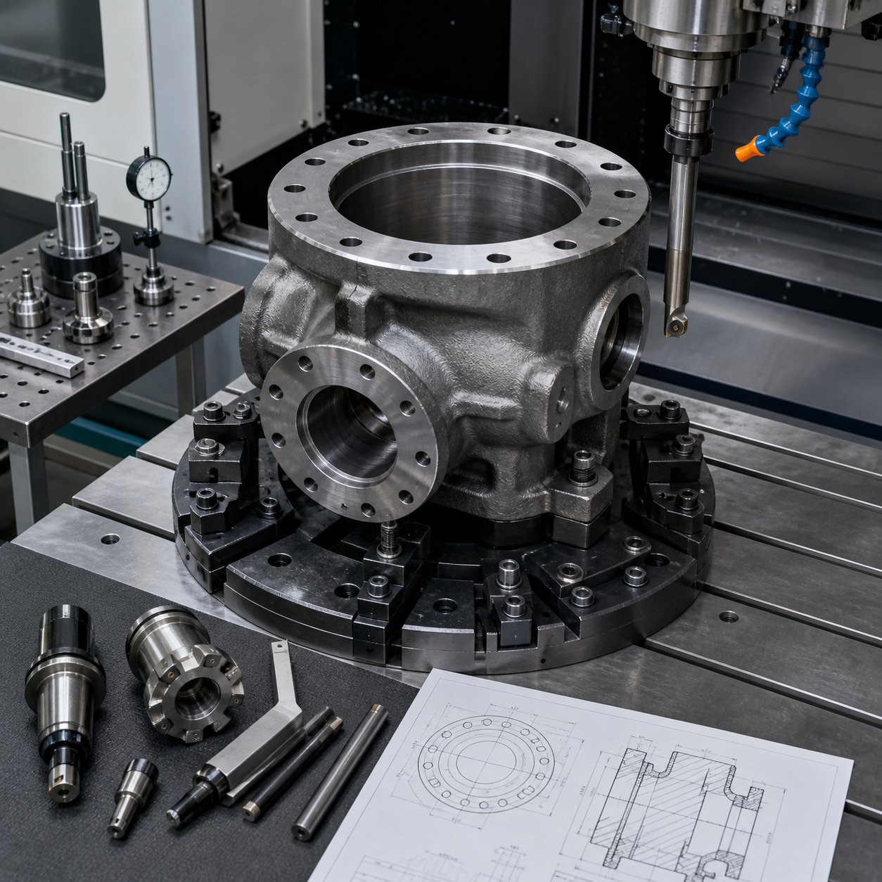
This CNC case study examines a cast steel valve bonnet with a main gasket flange, a large central bore, a side port and a twelve-hole bolt circle. The example drawing requires 0.05 mm flatness on the sealing face, 0.04 mm bore-to-flange perpendicularity and reliable thread depth in the blind bolt holes. Casting stock is uneven, so the first decision is how to establish a repeatable datum without chasing the rough surface.
Cast steel valve parts combine interrupted cuts, scale, variable hardness and heavy workholding. A process that works on clean bar stock may fail on a casting because the first pass shocks the insert and the part may sit differently after each unclamp. The machining plan should create clean datums early and protect the sealing face until major stock removal is complete.
Workholding and Datum Setup
Use the rough flange only for the first clamping operation. Indicate from the cast bore and outside bosses to distribute stock, then face a temporary datum ring and rough the central bore. For the second setup, locate on the machined ring and use robust toe clamps or a custom fixture plate that supports the flange near the bolt circle.
Before finishing, verify that the gasket face has enough stock after cleanup. If the casting is tilted, forcing it flat with clamps can hide the problem until inspection. A three-point support strategy with measured shim correction is often better than simply adding clamping force.
Tooling Plan
| Operation | Suggested tool | Purpose |
|---|---|---|
| Casting skin cleanup | Negative rake face mill with tough coated inserts | Survives scale and interrupted entry |
| Flange semi-finish | 45-degree face mill or high-feed cutter | Controls cutting force on the supported flange |
| Main bore roughing | Rigid boring bar with strong insert geometry | Handles variable stock and maintains bore direction |
| Main bore finish | Fine boring head with wiper-capable insert | Controls size, roundness and surface finish |
| Bolt circle | Indexable drill or carbide drill, thread mill for critical threads | Improves location and avoids broken taps in expensive castings |
Starting Parameters
For initial face milling on cast steel, trial around 120-180 m/min, 0.08-0.16 mm per tooth and moderate depth of cut with a tough insert grade. Boring can begin near 90-140 m/min with feed adjusted to bar diameter and overhang. For bolt holes, choose parameters from the drill supplier, then confirm chip evacuation at full depth before committing to a production cycle.
The most important rule is stable engagement. Heavy interrupted impact at the casting skin can chip an insert long before normal flank wear appears. Use a conservative first pass, then increase only after the skin and hard spots are understood.
Process Sequence and Quality Gates
- Inspect casting stock, parting-line mismatch and visible defects.
- Create a temporary datum ring and rough the main bore.
- Reverse onto the machined datum and support the flange near the bolt circle.
- Rough the sealing face, OD and bore while leaving finishing stock.
- Drill bolt holes after the flange datum is stable.
- Finish bore and gasket face in the same controlled setup when possible.
- Thread mill or tap with torque monitoring and chip control.
- Inspect flatness, bore size, perpendicularity, bolt circle position and thread depth.
For SEO value, the practical keyword group is cast steel valve bonnet CNC machining, flange facing, boring and bolt circle tooling. The article gives a useful route without hiding the need for casting-specific inspection data.