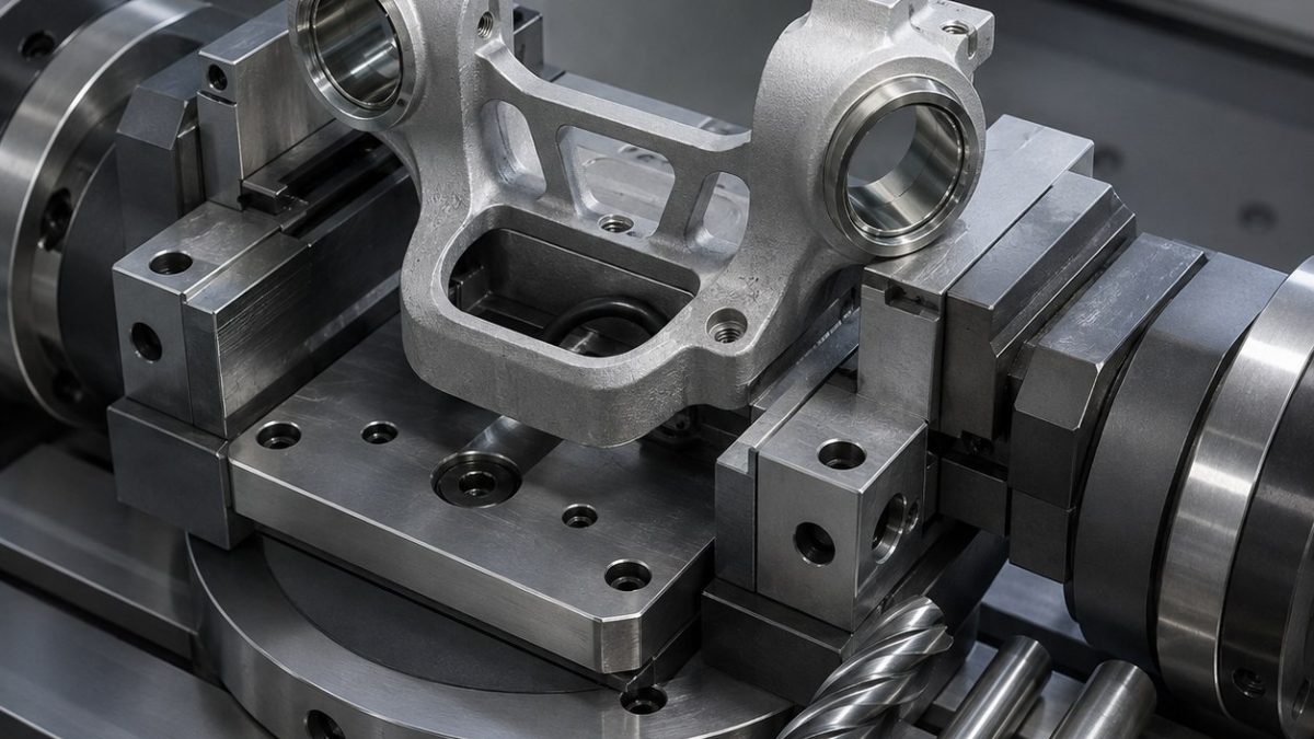
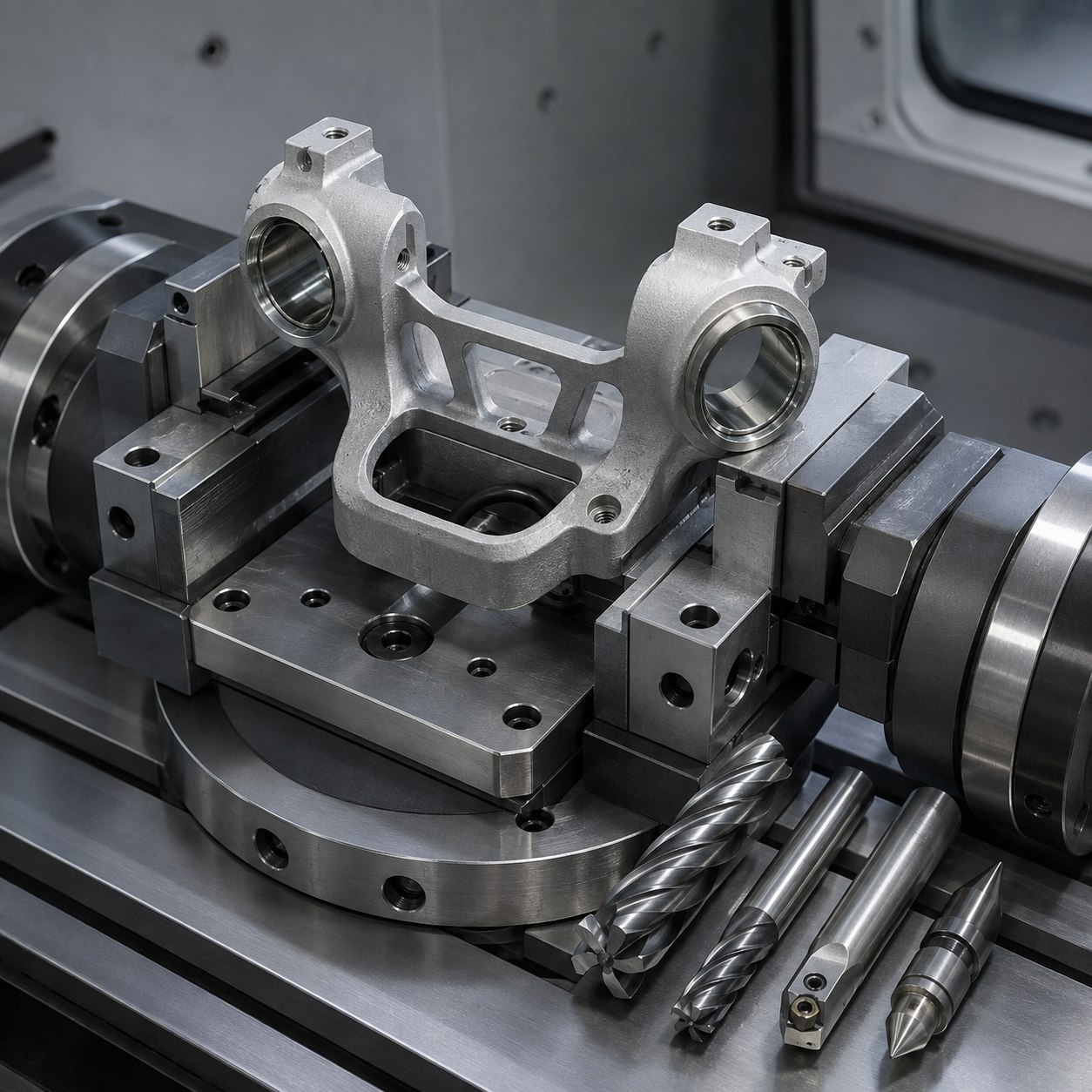
English: ZA-27 Gimbal Housing Tooling
This ZA-27 housing case shows how to hold coaxial opposed bearing bores while a cable pocket leaves a thin bridge. The cutter plan separates casting cleanup, bore correction and low-force wall finishing.
Drawing decisions
| Drawing zone | Selected carbide tool | Why and rejected alternative |
|---|---|---|
| Datum face and casting skin | Ø32 high-positive PCD face mill | Cleanly cuts zinc-rich alloy; a heavy honed steel insert is rejected because it smears. |
| Opposed bearing bores | Ø12 carbide pilot, modular fine boring head, balanced short holder | Boring corrects cast-core position and controls coaxiality. |
| Cable pocket | Ø8 3-flute polished carbide rougher plus Ø4 corner-radius finisher | Large flute space prevents chip welding and preserves the thin bridge. |
| Thin bridge edges | Ø3 2-flute polished carbide, alternating side passes | Balanced stock release limits bridge pull and burr rollover. |
| Threaded mounts | Carbide drill, thread mill and compact back-chamfer tool | Thread milling reduces tap breakage in a thin, irregular wall. |
Process, roughing and finishing
Use cast pads for the first location, probe both bore bosses, rough the pocket in a symmetric sequence, and finish bores from a trunnion setup without releasing the soft jaws. Alternate bridge-side passes, use air-rich coolant for chip evacuation, and keep PCD away from interrupted steel fixture contact. Related reading: tool-overhang control and precision bore finishing.
Inspection and tool-life gate
Check each bearing bore for size and roundness, then measure their common-axis error without unclamping. CMM checks threaded-hole position to the bore axis; an optical edge check grades bridge burrs. Release from the fixture and repeat bridge flatness to expose clamp distortion.
Practical FAQ
Why is the smallest tool not used for the whole feature?
A larger rigid cutter removes stock and controls heat; the small tool is reserved for access-limited finishing.
When should an offset be changed?
Only after measurements show a stable directional error rather than changing deflection or edge wear.
What releases the part?
Functional geometry, surface finish, burr condition and datum relationships must all pass inspection.


