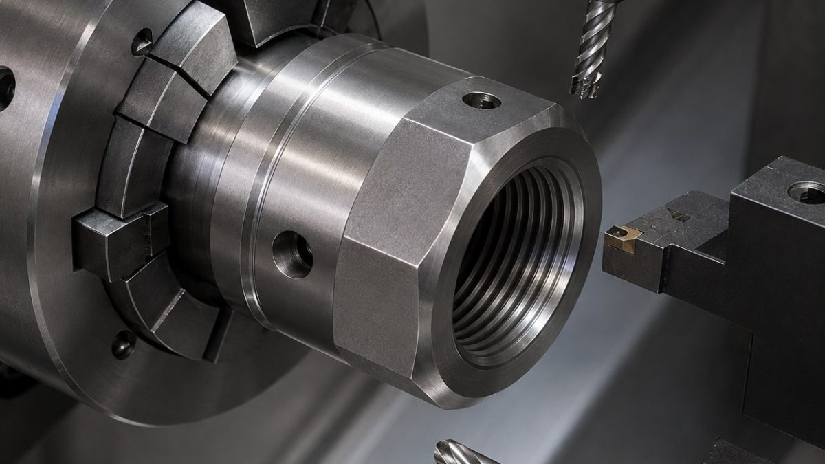
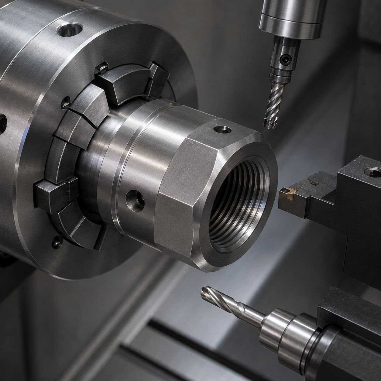
English: Nitronic 60 Valve Stem Nut Tooling
This hypothetical valve stem nut answers how to machine a deep internal ACME thread in galling-resistant Nitronic 60 while keeping lubricant paths open. Stable engagement, positive cutting edges and intersection burr control govern the tooling package.
Drawing decisions
| Drawing zone | Selected carbide tool | Why and rejected alternative |
|---|---|---|
| Blank and flats | Ø12 5-flute AlTiN variable-pitch carbide end mill, small hone | Resists work hardening while avoiding the rubbing of a dull general-purpose cutter. |
| Deep ACME thread | Single-profile carbide thread mill, TiAlN, hydraulic holder, radial passes | Lower torque and adjustable pitch diameter; a form tap is rejected for seizure risk. |
| Lubricant groove | 2 mm carbide grooving insert with sharp positive geometry | Controls groove width without smearing the sidewalls. |
| Cross grease holes | Carbide stub drill plus through-coolant long drill and back-chamfer tool | Pilot stability and intersection deburring prevent a blocked oil path. |
| Entry chamfer | 90° 3-flute carbide chamfer mill, short reach | Separates lead geometry from thread tool wear. |
Process, roughing and finishing
Turn the reference face and OD in one collet setup, mill flats only after the bore axis is established, interpolate the ACME thread from bottom outward, then drill grease holes from supported faces. Use high-pressure coolant and no dwell at reversals; inspect chips for blue rubbing before allowing offset correction. Related reading: tool-overhang control and precision bore finishing.
Inspection and tool-life gate
Verify major and pitch diameters with a functional ACME gauge and CMM flank points, measure lead over the working length, pin-check cross-hole breakthrough, borescope the groove intersections and record Ra 1.6 µm on loaded flanks. A stable size shift may be corrected; changing taper signals tool deflection or wear.
Practical FAQ
Why is the smallest tool not used for the whole feature?
A larger rigid cutter removes stock and controls heat; the small tool is reserved for access-limited finishing.
When should an offset be changed?
Only after measurements show a stable directional error rather than changing deflection or edge wear.
What releases the part?
Functional geometry, surface finish, burr condition and datum relationships must all pass inspection.


