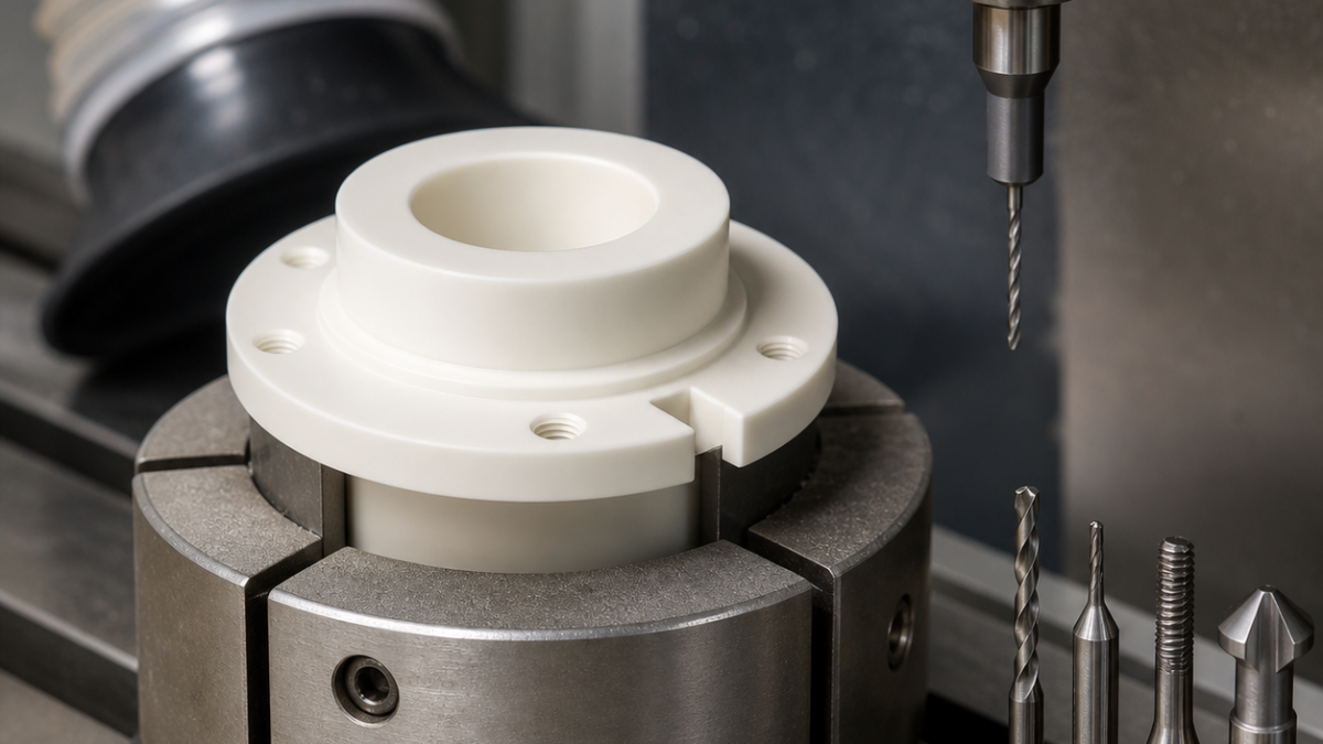
English: Macor Vacuum Feedthrough Insulator CNC Tooling Case: Thin Flange and Threaded Holes
Macor tooling should be selected by the failure it must prevent. Powder at a hole exit points to unsupported drilling, crescent chips at the flange point to excess radial force, and torn ceramic threads point to a tap wedging in a blind hole. For this hypothetical vacuum-feedthrough insulator, PCD defines the concentric seal geometry, stub carbide drills create supported pilots, and a single-row carbide thread mill avoids tap torque.
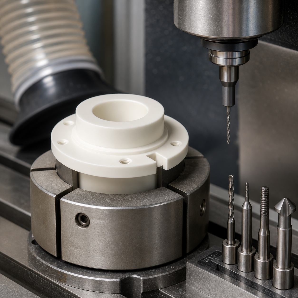
Functional geometry and permissible edge condition
Seal shoulder A is the primary datum, central bore B establishes the conductor axis, and anti-rotation slot C clocks four M3 holes. The Ø24 bore is H8, A-to-B concentricity is 0.035 mm, the 2.6 mm flange is flat within 0.030 mm, and the shoulder finish is Ra 1.6 µm. All vacuum-side edges require a 0.15 ±0.05 mm chamfer; a visually tiny uncontrolled chip outside that band is unacceptable because it can create a leak path or assembly stress point.
Tool trial matrix: feature, signature and final selection
| Drawing operation | Selected tool and holder | Rejected trial / failure signature |
|---|---|---|
| Seal face and outside diameter | PCD-tipped positive turning tool, R0.2 nose, polished rake, rigid miniature boring-bar holder | General-purpose honed carbide produced radial crushing and a chalky edge at the flange. |
| Ø24 H8 central bore | Ø12 two-flute diamond-coated carbide end mill, short flute, helical interpolation in a shrink holder | A full-diameter drill created an exit ring chip; interpolation keeps force tangent and leaves correction stock. |
| 2.6 mm flange contour | Ø6 two-flute diamond-coated fine-grain carbide, 20° low-helix geometry, 8 mm flute, hydraulic micro chuck | A high-helix four-flute cutter lifted the unsupported flange and produced crescent breakouts. |
| M3 blind-hole pilots | Ø2.5 stub solid-carbide drill, 130° point, double-margin, 6 mm flute, precision collet | A long jobber drill flexed and peck impacts marked the hole mouth. |
| M3 internal threads | Ø1.9 single-row micrograin-carbide thread mill, uncoated sharp edge, hydraulic micro chuck | A forming tap is rejected outright; a cutting tap also wedges chips and applies burst torque to the ceramic. |
| 3 mm anti-rotation slot | Ø2.5 two-flute diamond-coated carbide, straight flute, 4 mm cutting length | A long spiral tool pulled a chip from the slot exit. |
| Vacuum-side chamfers | Ø6 PCD 90° two-edge chamfer tool, preset axial height | Hand stoning varied the edge break and obscured small cracks. |
How the fixture makes brittle machining possible
A ground polymer split collet supports the cylindrical land over nearly 300°, while a replaceable PEEK washer sits directly beneath the flange. Clamping torque is recorded; the collet is never tightened by visual feel. The seal face is cut first, the bore is interpolated from both ends with 0.10 mm overlap away from the functional shoulder, and the flange contour is finished in shallow axial levels toward the support. Blind holes use a smooth feed with full withdrawal for vacuum extraction rather than impact pecking.
Machining is dry under source extraction qualified for fine ceramic dust; compressed-air blasting across the operator or guideways is prohibited. Edge-chip growth, spindle-load spikes and a change from granular to plate-like debris are tool-change signals. The thread mill makes a rough orbit and a compensated finish orbit, then exits along the bore center. No metal screw is used as an in-process gauge while the part is clamped.
Inspection without creating the defect being measured
A low-force optical system measures the flange edge, chamfer width, slot exit and hole mouths before contact inspection. The CMM uses a small calibrated force to build A-B-C and checks the bore at two depths. Threads are evaluated optically and with a polymer master at limited torque; a metal GO plug is reserved for the approved final method. Flatness is measured on three compliant supports, and the finished assembly receives the specified helium-leak test only after cleaning.
What tool should machine Macor blind threads?
A small single-row carbide thread mill avoids tap wedging and permits separate rough and finish diameter compensation.
How can a thin Macor flange be machined without edge chipping?
Support it immediately underneath, use a low-helix two-flute diamond-coated cutter, shallow axial levels and a toolpath directed toward the support.
Should Macor dust be blown away with shop air?
No. Capture it at source with the facility’s qualified extraction and cleaning process; uncontrolled air spreads abrasive fine dust.
For contrast, see post-sinter alumina edge control and dry dust management around fragile features.
中文: Macor真空馈通绝缘件配刀:薄法兰、盲螺纹与崩边控制
Macor配刀应从失效迹象反推:孔出口出现粉化环,说明钻削缺少背衬;法兰出现月牙崩口,说明径向力或上提力过大;盲螺纹撕裂,则通常是丝锥楔紧。本假设真空馈通件采用PCD建立同心密封几何,短型硬质合金钻加工受控底孔,单排牙硬质合金螺纹铣刀避免攻丝扭矩。
图纸功能和允许边缘
A为密封肩,B为Ø24 H8中心孔,C防转槽定义四个M3孔方向。A-B同心度0.035 mm,2.6 mm法兰平面度0.030 mm,密封肩Ra 1.6 µm。真空侧全部边缘要求0.15 ±0.05 mm倒角;即使很小的失控崩口,也可能形成泄漏通路或装配应力点。
刀具试验矩阵:特征、失效与最终配刀
| 图纸特征 | 最终刀具与刀柄 | 淘汰试验及迹象 |
|---|---|---|
| 密封面与外圆 | PCD刀尖正角车刀,R0.2,抛光前刀面,微型刚性刀杆 | 通用钝化硬质合金会在法兰边产生粉化压碎。 |
| Ø24 H8中心孔 | Ø12两刃金刚石涂层硬质合金,短刃,热缩刀柄螺旋插补 | 全直径钻在出口形成环状崩边;插补可保持切向受力并留修正量。 |
| 2.6 mm法兰轮廓 | Ø6两刃金刚石涂层细晶刀,20°低螺旋,刃长8 mm,液压微夹头 | 高螺旋四刃刀会抬起法兰并产生月牙缺口。 |
| M3盲孔底孔 | Ø2.5短型整体硬质合金钻,130°钻尖,双刃带,刃长6 mm | 长钻摆动,冲击式啄钻在孔口留下微裂纹。 |
| M3内螺纹 | Ø1.9单排牙微粒硬质合金螺纹铣刀,锋利无涂层,液压微夹头 | 挤压丝锥禁止使用,切削丝锥也会堵屑并对陶瓷施加胀裂扭矩。 |
| 3 mm防转槽 | Ø2.5两刃金刚石涂层直槽刀,刃长4 mm | 长螺旋刀在出口向上拉出崩口。 |
| 真空侧倒角 | Ø6双刃PCD 90°倒角刀,预调轴向高度 | 手工油石会让倒角宽度漂移并掩盖裂纹。 |
夹具、刀路和粉尘控制
磨制聚合物开口夹套以近300°包住圆柱面,法兰正下方放可更换PEEK垫圈,夹紧扭矩记录在工艺卡中。先加工密封面,中心孔从两端插补并在非功能区重叠0.10 mm;法兰按浅轴向层次朝支承方向精轮廓。盲孔采用平稳进给并完全退出吸尘,不用冲击式频繁啄钻。
加工区采用经确认的源头吸尘,禁止用压缩空气把细陶瓷粉吹向人员和导轨。崩边扩大、负载尖峰、碎屑由颗粒状变成片状,均触发换刀。螺纹铣刀先做开粗圆周,再做直径补偿精圆周并沿孔中心退出。
避免检验本身造成缺陷
先用低力光学系统测法兰边缘、倒角宽度、槽出口和孔口,再进行接触测量。三坐标以低测力建立A-B-C并在两个深度测中心孔。螺纹先光学检查,再用限扭聚合物主件轻配;平面度在三个柔性支点上测量,清洗后才做图纸规定的氦检漏。
Macor盲螺纹用什么刀?
单排牙硬质合金螺纹铣刀避免丝锥楔紧,并可分别补偿粗、精直径。
薄Macor法兰怎样避免崩边?
法兰下方就近支承,使用低螺旋两刃金刚石涂层刀,分浅层并让刀路朝支承方向。
能用气枪吹Macor粉尘吗?
不能;应按车间确认的吸尘与清洁流程源头捕集,避免磨蚀性细粉扩散。
对比阅读:氧化铝陶瓷边缘保护和脆弱特征的干式粉尘管理。
Français: Isolant Macor : outils pour bride mince et trous filetés
Le choix d’outil suit ici les défauts observables: poudre en sortie de trou, éclat en croissant sur la bride ou filet arraché. Le PCD définit l’étanchéité, des forets carbure courts créent les pilotes et une fraise à fileter évite le couple d’un taraud dans le Macor.
Fonctions du plan
A est l’épaulement d’étanchéité, B l’alésage Ø24 H8 et C la rainure d’orientation. La concentricité vaut 0,035 mm, la bride de 2,6 mm tient 0,030 mm et les arêtes vide reçoivent 0,15 ±0,05 mm.
Matrice défaut–outil
| Fonction | Outil retenu | Essai refusé |
|---|---|---|
| Face et diamètre | Outil PCD positif R0,2, face polie | Le carbure honé écrasait l’arête. |
| Ø24 H8 | Carbure diamanté Ø12, 2 dents, coupe courte, interpolation | Un foret plein créait un anneau ébréché. |
| Bride | Ø6 diamanté, 2 dents, hélice 20°, mandrin hydraulique | Quatre dents à forte hélice soulevaient la bride. |
| Pilote M3 | Foret carbure court Ø2,5, pointe 130°, double listel | Le foret long vibrait au bord. |
| Filet M3 | Fraise carbure une rangée Ø1,9, arête vive | Le taraud coince les copeaux et écarte la céramique. |
| Rainure | Ø2,5 diamanté, 2 dents droites, coupe 4 mm | Une longue spirale arrachait la sortie. |
| Chanfreins | PCD Ø6, 90°, deux arêtes | La pierre manuelle masquait les fissures. |
Support, poussière et contrôle
Une pince polymère fendue entoure la pièce; une rondelle PEEK soutient la bride. Le contour progresse par niveaux vers l’appui. Les trous utilisent une avance lisse et une extraction à la source, sans soufflette. La fraise à fileter effectue une orbite d’ébauche puis une orbite compensée.
L’optique mesure d’abord les bords; la MMT travaille à faible force. Un maître polymère limité en couple vérifie les filets avant le contrôle final et l’essai hélium.
Quel outil pour le filet?
Une fraise carbure une rangée, sans couple de taraudage.
Comment sauver la bride?
Appui immédiat, faible hélice et faibles profondeurs.
Souffler la poussière?
Non, il faut la capter à la source.
Voir l’alumine après frittage et la gestion des poussières sèches.
Русский: Изолятор Macor: тонкий фланец и глухая резьба
Инструмент выбирается по отказу: порошковый выход отверстия означает отсутствие опоры, серповидный скол — большую радиальную силу, сорванная резьба — заклинивание метчика. PCD формирует уплотнение, короткие карбидные сверла делают пилоты, резьбофреза исключает крутящий момент метчика.
Требования чертежа
A — уплотнение, B — Ø24 H8, C — установочный паз. Соосность 0,035 мм, фланец 2,6 мм имеет плоскостность 0,030 мм, вакуумные кромки получают фаску 0,15 ±0,05 мм.
Матрица дефект–инструмент
| Элемент | Инструмент | Отказ альтернативы |
|---|---|---|
| Плоскость | Позитивный PCD R0,2 | Хонингованный карбид дробил край. |
| Ø24 | Алмазное покрытие Ø12, 2 зуба, интерполяция | Полное сверло давало кольцевой скол. |
| Фланец | Ø6, 2 зуба, 20°, гидропатрон | Высокая спираль поднимала фланец. |
| Пилот M3 | Короткое карбидное Ø2,5, 130°, двойная ленточка | Длинное сверло вибрировало. |
| Резьба M3 | Однорядная карбидная резьбофреза Ø1,9 | Метчик клинит и распирает керамику. |
| Паз | Ø2,5, 2 прямых зуба, длина 4 мм | Спираль вырывала выход. |
| Фаски | PCD Ø6, 90°, две кромки | Ручной камень скрывал трещины. |
Опора, пыль и контроль
Разрезная полимерная цанга охватывает корпус, шайба PEEK поддерживает фланец. Контур идёт мелкими слоями к опоре. Пыль удаляется местной вытяжкой, не воздухом. Резьбофреза делает черновую и компенсированную орбиты.
Сначала оптика проверяет края, затем КИМ с малой силой. Полимерный образец с ограничением момента контролирует резьбу до финального гелиевого теста.
Чем делать резьбу?
Однорядной карбидной резьбофрезой.
Как защитить фланец?
Близкой опорой, малой спиралью и мелкими слоями.
Можно ли сдувать пыль?
Нет, её захватывают у источника.


