Related tooling references: Hardened D2 Trim Die Stripper Plate CNC Tool Selection for Slug Windows and Guided Punch Bores and Aluminum Nitride Power Module Carrier CNC Tool Selection for Isolation Pockets and Fragile Ribs.
English: GG25 Vacuum Pump Cover Tooling for Spiral Groove and Dowel Bores
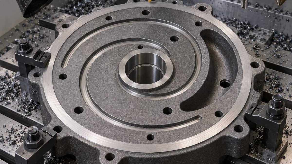
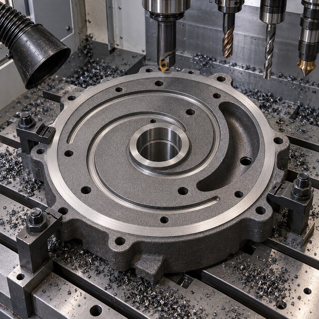
This GG25 vacuum pump end cover case answers how to select carbide tooling when the drawing mixes a spiral seal groove, dowel bore grid, bearing register and gasket land. The part looks simple, but the sealing path forces the machining plan to protect flatness and groove continuity.
Pump-cover print callouts converted to carbide tools
| Drawing feature | Carbide tool package | Control reason |
|---|---|---|
| Spiral seal groove | 2.5 mm TiCN carbide keyseat end mill with controlled radial step | A form tool is rejected because groove width changes along the spiral. |
| Dowel bore grid | Carbide drill, reamer, then adjustable fine boring on datum holes | Interpolation alone is too slow and risks graphite dust recutting. |
| Bearing register | Fine boring head with wiper insert and rigid boring holder | End-mill circular milling is rejected for roundness on abrasive iron. |
| Crescent oil pocket | 6 mm carbide rougher and 4 mm radius finisher | Avoids tearing the pocket edge into the gasket land. |
| Gasket land | Positive carbide face mill with dry dust extraction | Coolant mud is rejected because graphite slurry hides scratches. |
Machining order for sealing stability
Face the gasket land first, rough the oil pocket without touching the land edge, finish the bearing register, then cut the spiral groove with a dedicated small cutter. Dowel holes are made from the same datum setup so the cover locates repeatably before final deburring.
Cast iron dust, groove and bore-life controls
GG25 gray iron cuts freely but graphite dust recuts grooves and hides scratches. The process uses dry extraction, positive carbide, short tool overhang and replacement based on register size drift rather than sound. Coolant is avoided on the sealing face because slurry can mask damaged lands.
Flatness, bore and leak-path inspection
Inspection includes CMM dowel grid position, air-gauge or bore-gauge register size, surface plate blue check on the gasket land and optical review of the spiral groove. The cover is acceptable only if no chipped groove lip crosses the intended leak barrier.
Pump cover tooling FAQ
Why machine the spiral groove after the bearing register?
The register stabilizes datum control, while a late groove avoids recutting graphite across the seal path.
Is coolant useful on GG25 sealing faces?
Usually not here; dry extraction avoids graphite slurry hiding scratches.
What rejects the end cover?
A chipped groove lip, register roundness error or gasket-land scratch crossing the leak barrier.


