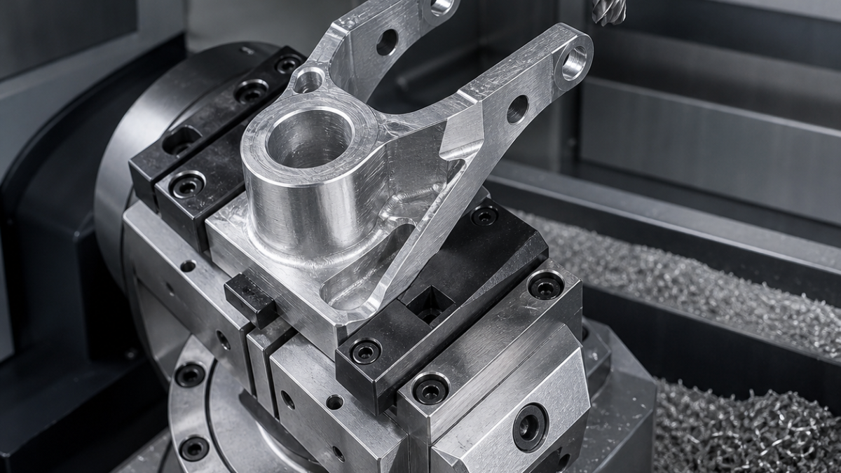
English: AZ91D Magnesium Gimbal Yoke CNC Case: Thin Arms, Pivot Bore and Chip-Fire Control
Search intent answered: machining an AZ91D magnesium gimbal yoke succeeds when the two slender arms remain supported until the pivot bores are finished, the bore axis is established from functional datums rather than the raw casting, and dry chips are removed continuously under a magnesium-specific fire plan. This hypothetical case explains a defensible route from drawing review to inspection without claiming production history.
Read the drawing as a stiffness problem
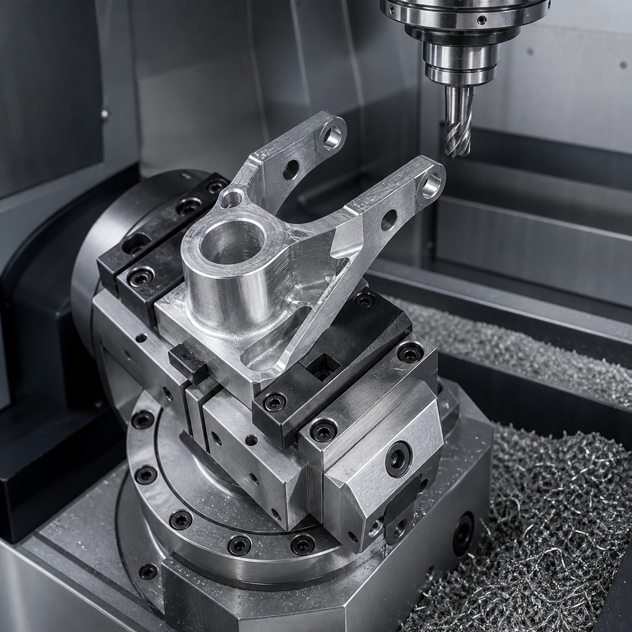
The drawing defines datum A on the mounting pad, datum B on the central pilot and datum C on one clocking hole. The 96 mm arm span carries two Ø12 H7 pivot bores with a 0.03 mm common-axis requirement to A; arm thickness is 4.5 mm, pad flatness is 0.05 mm and the finished pocket floor is 1.8 mm. A blanket profile tolerance would be misleading: the bore relationship governs motion, while outside arm contours mainly preserve clearance. Stock is therefore left on the arms until the pivot line is complete.
Carbide tools and a fire-aware cutting environment
Sharp polished uncoated carbide is selected: a three-flute high-helix end mill for open pockets, a short two-flute cutter for floor corners, a carbide drill followed by a fine boring head for each pivot bore, and a 45-degree carbide chamfer tool. Edge hone must be minimal because rubbing raises heat. Dry air blast and a dedicated vacuum rated for combustible metal dust evacuate chips; water-based coolant is not casually introduced. Class D extinguishing media, clean sumps and segregated chips are process requirements, not afterthoughts.
Two fixtures, one controlled release
Operation 10 clamps the casting on three sacrificial pads and machines A, the pilot and clocking hole. Operation 20 locates on those finished features in a nest with removable supports beneath both arms. Adaptive roughing uses constant engagement, climb cutting and a shallow axial step to avoid grabbing. Pockets are opened symmetrically left-right so residual stress is not released on one arm alone. A 0.4 mm radial and 0.25 mm floor allowance remain.
The pivot bores are drilled undersize, circular-interpolated and finish bored in one indexed setup. Support buttons stay engaged during boring. Only after the axis passes an in-process probe check are the outside profiles and support tabs removed. A spring pass at full finishing feed is avoided; instead, a measured wear offset controls size. Final contours use a short polished carbide end mill with low radial engagement and a single directional finish pass for Ra 1.6 µm.
Chip control, burrs and tool-life signals
Small dry chips are desirable, but recutting is not. Air nozzles aim away from cavities and extraction is verified before the spindle starts. Long dwell marks, a rising spindle-load trend or a grey smeared edge indicate a dull cutter. Tools are retired by edge quality and load trend rather than an invented fixed part count. Bores receive a light front-and-back chamfer; abrasive hand blending near the thin arms is prohibited because it can alter the datum relationship.
Inspection plan tied to function
A surface plate confirms pad flatness before release. A CMM builds A-B-C, measures both bore cylinders and reports their common axis, span and perpendicularity. Air gauging or certified plug gauges verify Ø12 H7 after temperature stabilization. Arm thickness is mapped at root and tip, and a fixture-mounted indicator compares free-state deflection before and after support removal. Visual inspection also confirms no embedded chip, smeared edge or ignition damage.
FAQ
Should AZ91D magnesium be flood cooled during CNC milling?
Not by default. The machine, coolant chemistry and fire controls must be qualified for magnesium; this case uses dry cutting with continuous approved extraction.
How do you keep thin gimbal arms from moving?
Finish functional datums first, support both arms locally, rough symmetrically, retain tabs and remove supports only after the common pivot axis is complete.
Why bore the pivot holes instead of reaming them?
Fine boring lets the process correct position and coaxiality from the established datum frame; a reamer mainly follows the existing hole.
Related process planning: coaxial lug-bore control and thin-wall pocket support.
中文: AZ91D镁合金云台叉架加工:薄臂、同轴孔与镁屑防火
搜索问题先回答:AZ91D镁合金云台叉架的关键不是单纯追求高速,而是先建立安装面—中心定位止口—定向孔基准,在两条薄臂仍受支撑时完成同轴枢轴孔,并用适用于可燃金属粉屑的连续抽排和D类灭火方案控制风险。以下为独立设计的假设案例,不代表真实客户项目。
把图纸拆成功能链
A基准为安装面,B基准为中心止口,C基准为定向孔。两只Ø12 H7孔跨距96 mm,相对A的公共轴线要求0.03 mm;臂厚4.5 mm、薄底1.8 mm、安装面平面度0.05 mm。先保证轴线和安装面,再处理非功能外形,避免把一般轮廓度误当作最高优先级。
刀具与安全边界
开粗采用锋利、抛光、无涂层三刃硬质合金立铣刀,局部薄底换短悬伸两刃刀;枢轴孔先用硬质合金钻头预孔,再圆插和精镗;边口用45°硬质合金倒角刀。钝刃摩擦会升温,因此以主轴负载和刃口涂抹状况换刀。干切配定向气流与经过可燃金属粉尘适用性确认的抽屑设备,机内不混入钢屑,并配置D类灭火介质。
对称去料和延迟释放
首序在铸造工艺台上加工A、B、C;第二序用三点支承巢式夹具定位,在两臂下放置可撤支承。自适应刀路保持恒定吃刀,左右腔交替去料,侧面留0.4 mm、底面留0.25 mm。两孔在同一分度状态下钻、圆插和精镗,在线测头确认轴线后才精铣臂外形并去除工艺连接。精加工采用小径向切宽和单向走刀,目标Ra 1.6 µm,不用无依据的空刀弹簧刀。
毛刺、刀寿命与检验
气嘴必须把镁屑吹离深腔而不是吹回切削区;负载上升、灰色拖抹边和异常亮痕都是换刀信号。孔口正反面只做轻倒角,薄臂附近禁止随意砂磨。检验时先在平台上复核A面,再由三坐标建立A-B-C并计算两孔公共轴线、跨距和垂直度;Ø12 H7用气动量仪或认证塞规复核,恒温后记录。臂根与臂尖分别测厚,拆除支承前后用指示表比较自由状态变形。
常见问题
镁合金铣削一定要用切削液吗?
不是。是否湿切取决于设备、液体兼容性及完整的镁加工防火评估;本案例采用连续抽屑的干切路线。
薄叉臂怎样避免回弹?
左右交替去料、保留连接、局部支撑,并在同轴孔完成后再释放非功能轮廓。
为何精镗而不是直接铰孔?
精镗可依据既定基准修正孔位和轴线,铰刀更容易沿随预孔偏差。
Français: Usinage d’une fourche AZ91D : bras fins, alésages coaxiaux et sécurité copeaux
Réponse à l’intention de recherche : pour usiner une fourche de nacelle en magnésium AZ91D, il faut conserver les deux bras soutenus jusqu’à la finition des pivots, construire l’axe depuis les références fonctionnelles et extraire les copeaux secs avec une installation qualifiée pour les métaux combustibles. Ce scénario est hypothétique et ne décrit aucun dossier client.
Lecture fonctionnelle du plan
La face d’appui A, le pilote B et le trou d’orientation C constituent le repère. Deux alésages Ø12 H7 espacés de 96 mm partagent un axe toléré à 0,03 mm par rapport à A. Les bras font 4,5 mm et le fond de poche 1,8 mm. L’axe des pivots prime donc sur le profil extérieur, qui reste avec surépaisseur tant que la rigidité est nécessaire.
Carbure tranchant et environnement maîtrisé
Une fraise carbure polie non revêtue à trois dents ouvre les poches; une fraise courte à deux dents finit les zones minces. Les pivots sont percés, interpolés puis alésés finement. Le faible rayon d’arête limite le frottement. L’air dirigé et l’aspiration homologuée évitent la recoupe; les copeaux sont séparés et un agent extincteur de classe D fait partie de la gamme.
Gamme et trajectoires
La première prise crée A-B-C. La seconde utilise un nid à trois appuis et des touches amovibles sous les bras. L’ébauche adaptative alterne gauche et droite avec engagement constant, en laissant 0,4 mm radialement et 0,25 mm au fond. Les deux pivots sont finis dans la même indexation, puis palpés avant la suppression des attaches. Une passe directionnelle à faible engagement vise Ra 1,6 µm.
Risques matière et contrôle
Une charge broche croissante ou une arête grise et étalée impose le remplacement de l’outil; aucune durée arbitraire n’est annoncée. Les chanfreins avant et arrière remplacent le ponçage manuel. Après stabilisation thermique, la MMT reconstruit A-B-C, calcule l’axe commun, l’entraxe et la perpendicularité. Un calibre certifié ou une mesure pneumatique confirme H7; l’épaisseur et la déformation libre sont relevées à la racine et en bout.
FAQ
Faut-il toujours lubrifier abondamment le magnésium AZ91D ?
Non. Le choix dépend d’une validation globale machine-fluide-incendie; ici, la stratégie est sèche avec extraction continue adaptée.
Comment limiter le déplacement des bras minces ?
En équilibrant l’ébauche, en gardant des attaches et des soutiens locaux, puis en libérant la pièce après les alésages.
Pourquoi choisir l’alésage fin ?
Il corrige position et coaxialité dans le repère fonctionnel, contrairement à un alésoir qui suit davantage l’avant-trou.
À rapprocher du contrôle d’alésages coaxiaux et du support des parois minces.
Русский: Обработка вилки AZ91D: тонкие рычаги и соосные отверстия
Краткий ответ: при обработке вилки подвеса из AZ91D тонкие рычаги оставляют поддержанными до расточки шарнирных отверстий, ось строят от рабочих баз, а сухую стружку непрерывно удаляют системой, допущенной для горючих металлов. Это гипотетический технологический пример без ссылки на заказчика.
Что определяет чертёж
База A — монтажная плоскость, B — центральный поясок, C — ориентирующее отверстие. Два отверстия Ø12 H7 с расстоянием 96 мм должны иметь общую ось в пределах 0,03 мм относительно A. Толщина рычагов 4,5 мм, дна кармана 1,8 мм. Поэтому ось отверстий важнее наружного контура, который сохраняет припуск для жёсткости.
Твердосплавный инструмент и пожарная дисциплина
Карманы обрабатывает острая полированная трёхзубая фреза без покрытия, тонкое дно — короткая двухзубая. Отверстия сверлят твердосплавным сверлом, интерполируют и растачивают. Малое притупление снижает трение. Направленный воздух и сертифицированная вытяжка не допускают повторного резания; стружку отделяют, рядом предусматривают средство тушения класса D.
Маршрут без преждевременного освобождения
На первой установке создают A-B-C. На второй деталь лежит в гнезде с опорами под обоими рычагами. Адаптивное черновое фрезерование чередует стороны, оставляя 0,4 мм по стенкам и 0,25 мм по дну. Оба отверстия заканчивают при одной индексации и проверяют щупом; затем удаляют перемычки и чистовым проходом получают Ra 1,6 мкм.
Износ, заусенцы и измерение
Рост нагрузки, серый размазанный край или блестящий след трения требуют замены фрезы. Вход и выход отверстий слегка фаскуют, ручное шлифование рычагов исключают. После выдержки КИМ строит A-B-C и рассчитывает общую ось, расстояние и перпендикулярность. H7 подтверждают пневмокалибром или поверенной пробкой; толщину и свободное отклонение измеряют у основания и конца рычага.
Вопросы и ответы
Нужна ли всегда СОЖ для AZ91D?
Нет. Решение принимают после оценки станка, жидкости и пожарной безопасности; здесь применено сухое резание с постоянной подходящей вытяжкой.
Как удержать тонкие рычаги?
Снимать материал симметрично, сохранять перемычки и локальные опоры, освобождая контур после расточки.
Почему не использовать только развёртку?
Расточка корректирует положение и соосность от рабочих баз, тогда как развёртка сильнее следует предварительному отверстию.
Смежные материалы: соосные проушины и опора тонких стенок.


