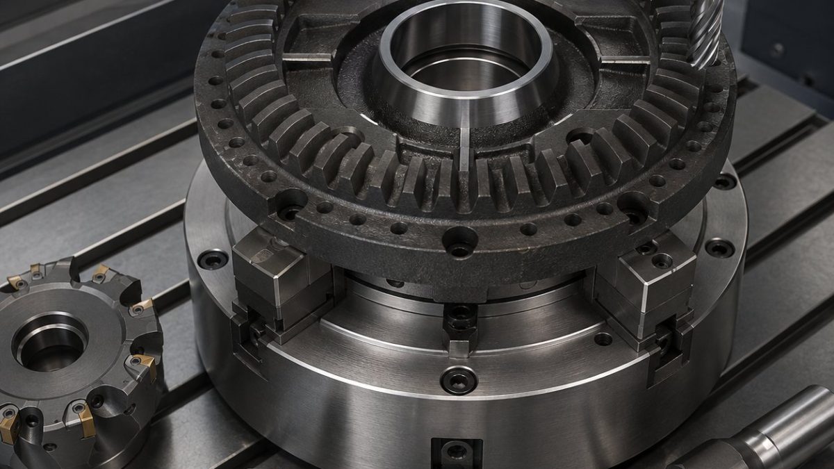
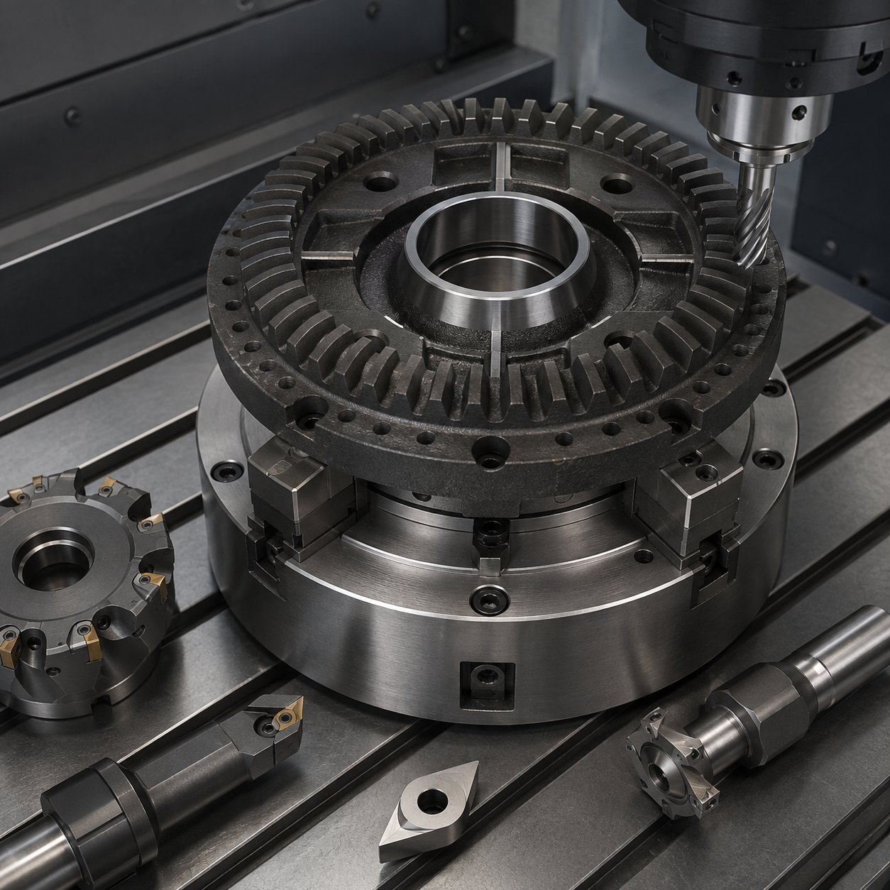
English: ADI Robot Reducer Output Flange CNC Tool Selection for Face Teeth and Tapered Bearing Seat
This case focuses on selecting carbide and CBN tools for an austempered ductile iron robot reducer output flange with curvic-style face teeth, a tapered bearing seat, bolt circle and cross oil grooves. The drawing challenge is to connect tooth contact, bearing geometry and oil-groove burr control without losing the flange axis.
Datum and machining logic
The bore is roughed first but not accepted as final until the face teeth and bearing seat are semi-finished. An expanding mandrel controls the axis while the face tooth pattern is indexed. Existing AXKXA bearing-axis thinking can be compared with AISI 4340 sheave bearing bore tooling and cast iron bearing housing tool selection.
Feature-to-tool selection
| Drawing feature | Tooling package | Reason for selection |
|---|---|---|
| ADI skin and rough flange | ISO-K/PVD carbide shoulder mill, strong edge prep | Handles graphite nodules and interrupted entry; sharp aluminium geometry is rejected. |
| Tapered bearing seat | Fine boring head with CBN or wear-resistant carbide insert | Maintains taper and roundness; reaming is rejected because taper correction is limited. |
| Curvic-style face teeth | Small ball end mill for root clearing plus form-relief carbide finisher | Separates root access from flank contact; one large form cutter risks chatter. |
| Cross oil grooves | Ø2 mm coated carbide end mill and controlled edge-break tool | Prevents loose burrs entering the bearing. |
| Bolt circle and spotfaces | Carbide drill, circular spotface interpolation, 90° chamfer mill | Keeps spotfaces square to datum A. |
Toolpath, burr and inspection plan
Use adaptive roughing on the flange pockets, indexed 3+2 machining for tooth spaces, spring passes only after the mandrel has stabilized, and dry air blast for cast-iron chips. Inspection checks bearing-seat taper, bore runout to face teeth, oil-groove burr height, tooth contact pattern and bolt-circle true position.


