
Related tooling references: Hardened D2 Trim Die Stripper Plate CNC Tool Selection for Slug Windows and Guided Punch Bores and Aluminum Nitride Power Module Carrier CNC Tool Selection for Isolation Pockets and Fragile Ribs.
English: Haynes 230 Igniter Boss Tooling for Angled Seal Cone and Cooling Holes
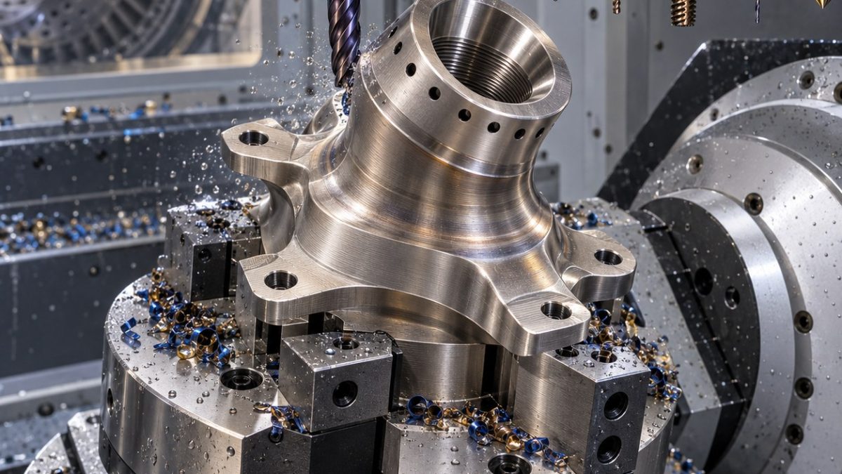
This Haynes 230 case answers a searcher’s practical question: which carbide tools should be chosen when an igniter boss drawing combines a sealing cone, tiny cooling holes and a thin hot flange. The drawing is read from the gas-seal features outward, because a shiny pocket is useless if the cone leaks or a hole exits with burr folded into the port.
Combustor boss drawing features mapped to tools
| Drawing feature | Specific carbide tool and holder | Why the plausible alternative is rejected |
|---|---|---|
| Angled seal cone | 10 mm 5-flute AlTiN carbide end mill for semi-finish plus 60° carbide form finisher in hydraulic holder | Ball-only surfacing is rejected because cusp direction can cross the seal path. |
| Cooling holes | 1.2 mm TiAlN carbide drill, through-coolant peck, carbide spot drill | EDM is rejected because recast cleanup would still need mechanical edge control. |
| Thin flange pads | 16 mm positive high-feed carbide cutter, small corner radius | A heavy face mill would bow the hot thin pad. |
| Ignition thread port | Carbide thread mill after circular interpolation | Tapping is rejected because nickel chips can seize in the blind wall. |
| Heat-shield shoulder | 6 mm corner-radius finisher with neck relief | Keeps reach without rubbing the cone wall. |
Sequence for nickel-alloy heat control
Rough the outside with the flange still supported, semi-finish the cone, drill cooling holes from the stable side, then thread-mill the ignition port after the shoulder is proven. The final cone pass is separated from holemaking so drill burrs are removed before the sealing surface is touched again.
Burr, chip and tool-life risks in Haynes 230
Haynes 230 behaves like a hot nickel alloy: rubbing hardens the edge, chips stay hot and small drills fail when coolant cannot enter. Tool life is judged by burr color, squeal at the cone exit and cooling-hole size drift; a safe program uses sharp edges, short contact time and no dwell at the thread relief.
Seal cone and cooling-hole inspection
Inspection checks cone angle with an optical comparator, port thread with a go/no-go gauge, cooling holes by pin and borescope, flange pads by height map and burrs under magnification. The hypothetical part is acceptable only when the cone remains continuous after deburring.
Igniter boss tooling FAQ
Why not ball-mill the Haynes 230 seal cone?
A ball tool can leave cusp direction across the sealing path; a form finisher gives a more predictable seal line.
Which feature drives tool choice first?
The angled seal cone, because burr cleanup and hole drilling must not damage it.
When is the small drill replaced?
When pin size drifts, burr color darkens or coolant no longer clears chips from the exit.
For the drill, holder, exit-support and burr-control decision behind this feature, use the Micro-hole decision hub.


