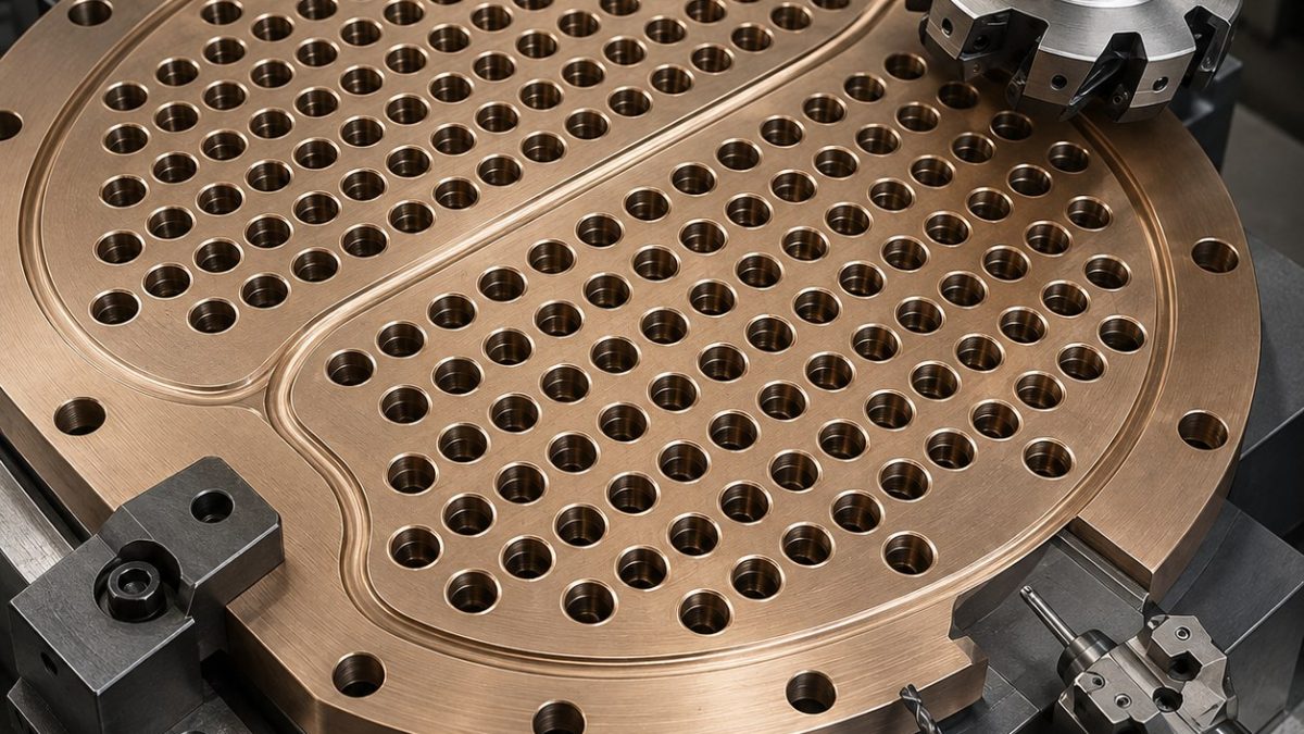
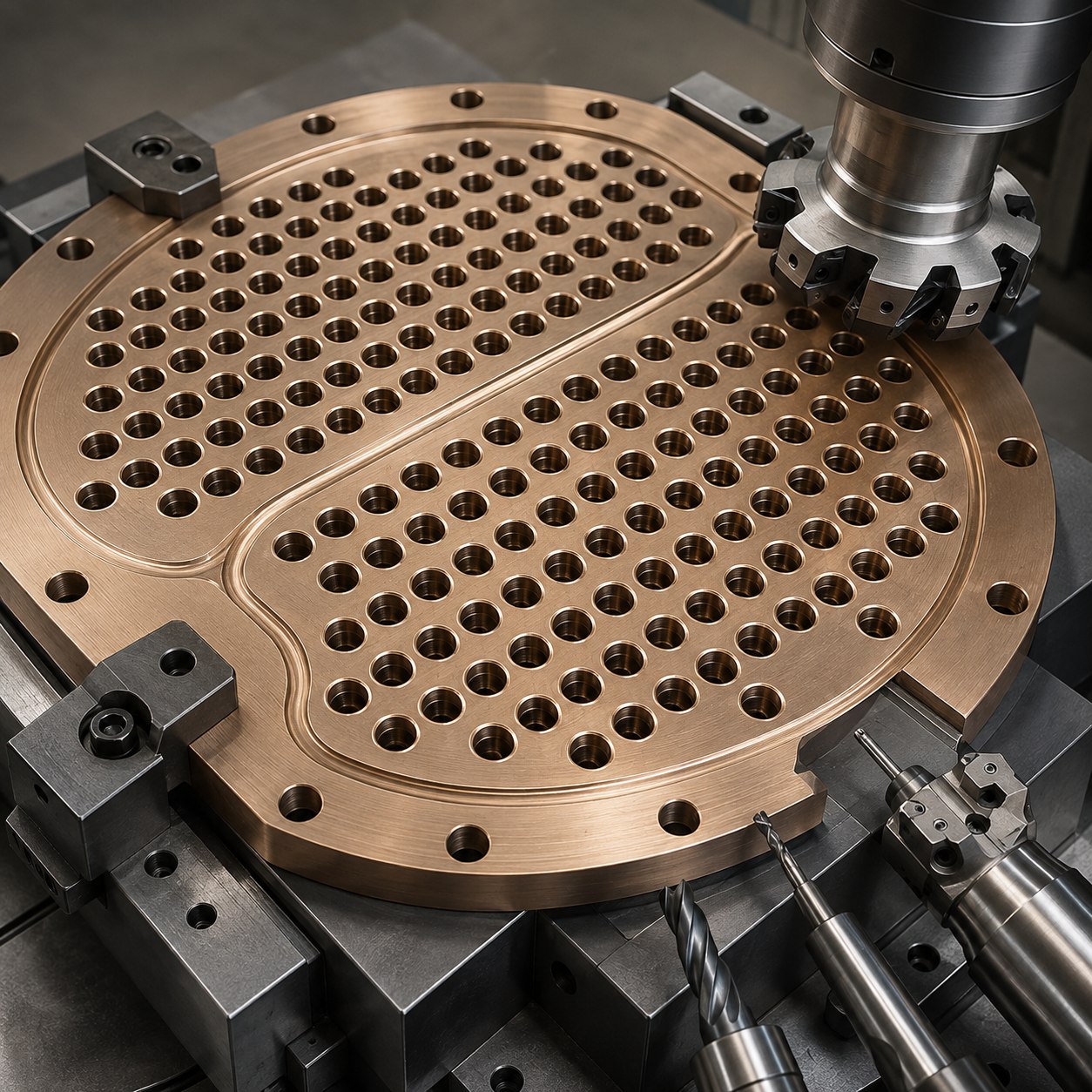
English: C70600 Condenser Tube Sheet Tooling for Bore Array and Retention Grooves
The drawing is treated as an array-control problem rather than a drilling cycle. Tube-hole position, groove depth and gasket-land flatness are released through separate tool-life gates.
Drawing feature-to-tool decisions
| Drawing feature | Tool, geometry and holder | Decision and rejected alternative |
|---|---|---|
| Tube-hole pilot and rough bore | Ø8 through-coolant 3-flute carbide drill, polished margin, 5×D | Stable entry and chip evacuation; a long HSS drill is rejected for wandering. |
| Final tube-hole size | Fine boring head with sharp uncoated carbide or PCD insert | Corrects array drift and holds diameter; reaming every hole would copy pilot error. |
| Internal retention groove | 1.2 mm full-radius carbide grooving tool in anti-vibration holder | Controls groove width and depth without rubbing the bore wall. |
| Partition gasket land | Ø40 PCD face mill with wiper edge, minimal runout | Produces flat sealing tracks without copper-nickel smearing. |
| Back chamfer and burr | Compact reverse-chamfer carbide tool | Removes exit burr without flipping the heavy plate repeatedly. |
Fixture and cutting sequence
Clamp on three ground support pads with a central jack, probe six reference holes, drill the array in thermal zones, then finish representative bores before releasing each zone. Mill the gasket land last with a constant-overlap face path.
Material, chip and tool-life controls
Flood coolant carries long copper-nickel chips through the drill; pressure and filter condition are logged by zone. Replace the drill when thrust rises 15% or bore taper changes, and reject dry recutting of packed chips.
Tolerance and surface verification
CMM checks the first, middle and last hole in every zone plus the partition boundary; air gauging confirms diameter and taper. Measure groove depth with a bore stylus, gasket land Ra 0.8 µm and full plate flatness after a 30-minute release.
Search questions answered
Why not ream every tube hole?
Fine boring can correct pilot drift and quantify tool wear; a reamer follows a displaced pilot and can hide array error.
How are internal grooves inspected?
Use a calibrated bore stylus on sampled holes and sectioned setup coupons before accepting the whole zone.
What prevents exit burrs?
Through-coolant drilling, sacrificial support where possible and a controlled reverse-chamfer pass.


