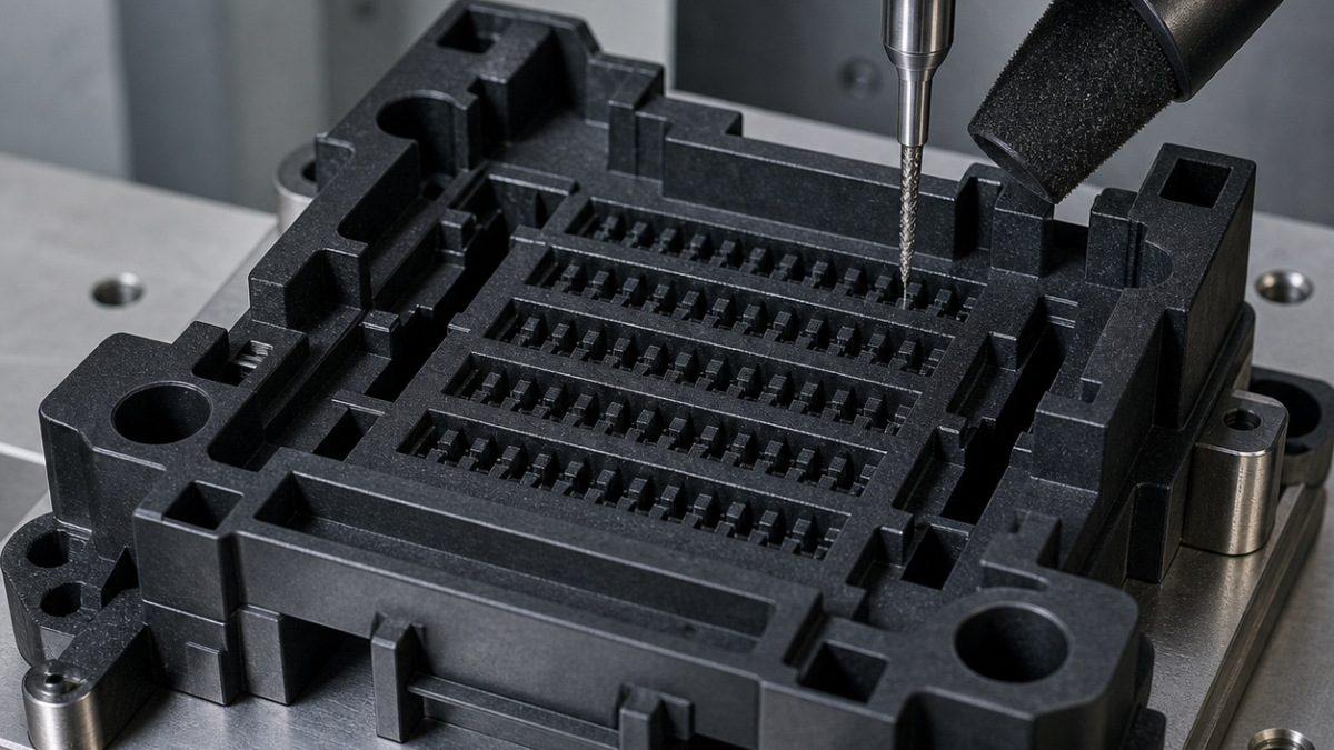
English: PBT-GF30 Connector Inspection Nest CNC Tool Selection for 0.60 mm Pin Pockets
A PBT-GF30 connector inspection nest fails when the tool leaves glass-fiber fuzz inside a 0.60 mm pin pocket or bends a latch wall that looks correct while clamped. The useful tooling answer combines diamond-coated carbide for abrasive walls, a polished low-helix finisher for the contact floors, and a fixture that supports the nest under every functional rail. This hypothetical case maps each drawing feature to a cutter and a verification method instead of treating glass-filled polymer as ordinary plastic.
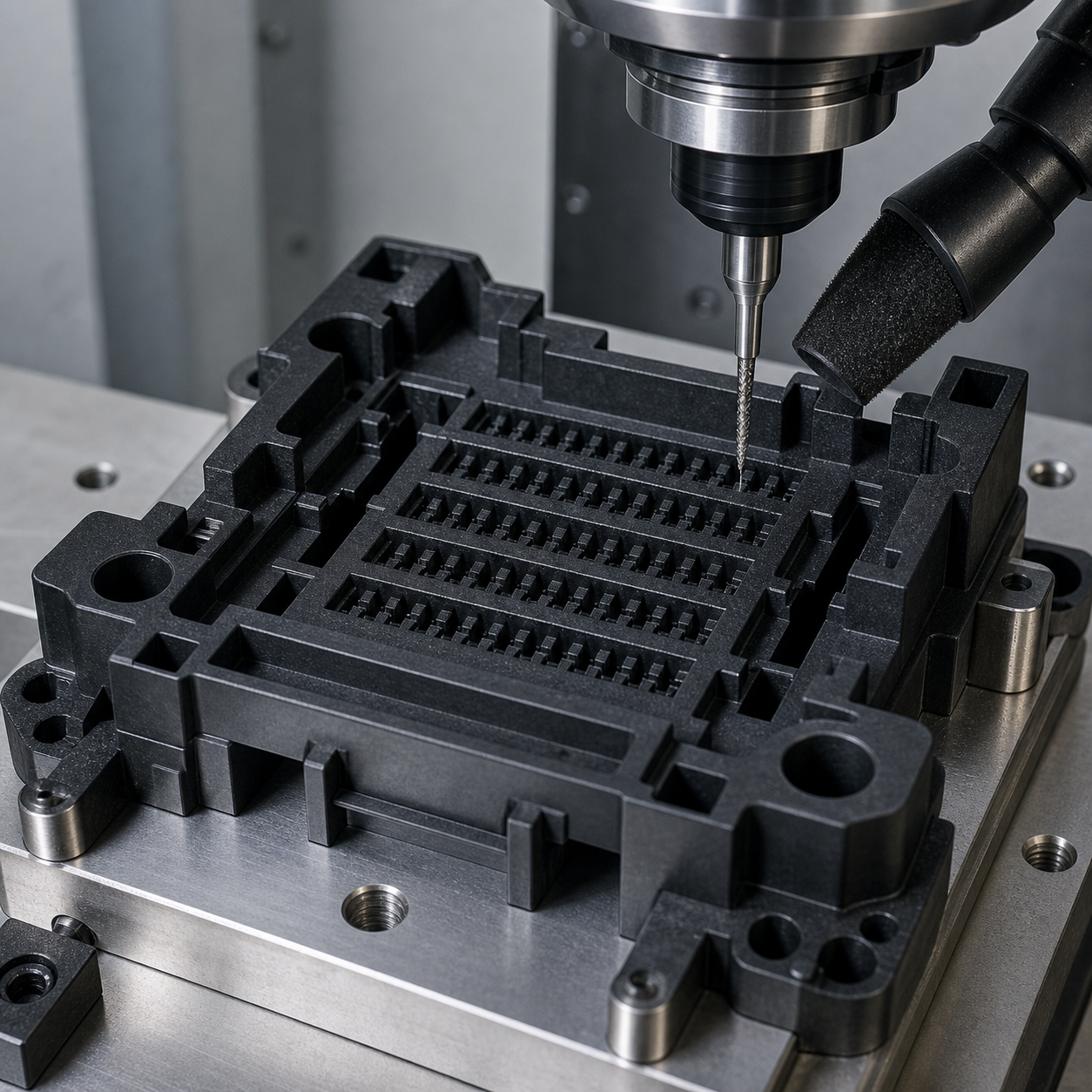
The connector decides which dimensions matter
Bottom face A seats on the inspection machine; Ø6 H7 bore B and a 6 mm slot C orient the nest. The centre field holds 48 rectangular pin pockets, each 0.600 +0.020/0 mm wide, 1.20 ±0.02 mm long and 6.00 ±0.03 mm deep, with true position 0.025 mm to A|B|C. Two latch windows are 1.50 ±0.03 mm wide. Four support rails stand 0.70 ±0.025 mm above the pocket floor, and the outer nest contour must leave 0.10–0.20 mm assembly clearance to a qualified master connector. Continuous fiber whiskers, a melted glaze or a raised floor burr are rejected.
The 30% glass-filled PBT designation describes a material family, not a single cutting behaviour. Fiber length, molding orientation, moisture conditioning and annealing can change breakout. Incoming blanks therefore include orientation marks, and the first-piece plan is qualified in both the strong and weak edge directions.
Feature-to-tool register with a quality signal
| Feature | Carbide selection and holder | Quality signal during cutting |
|---|---|---|
| A face and outside envelope | Ø10 two-flute diamond-coated carbide router, 20° compression geometry, 0.02 mm edge radius, short hydraulic chuck | Balanced top and bottom shear limits fiber lift. A bright glazed track indicates rubbing or excessive heat. |
| Large relief cavities | Ø4 three-flute diamond-coated carbide end mill, 30° variable pitch, R0.2, 10 mm reach, through-air shrink holder | Stable spindle load and short granular chips show adequate chip thickness; long softened strings trigger a feed and extraction check. |
| 0.60 mm pin pockets | Ø0.50 two-flute diamond-coated carbide micro end mill, 15° low helix, 6.5 mm necked reach, 4 µm edge preparation, ultra-precision shrink collet | Width is created by two compensated wall passes, not full slotting. Growing width taper or a fuzzy exit photograph retires the tool. |
| Pocket floors | Ø0.45 single-flute uncoated polished O-geometry carbide, R0.03, 1.0 mm cutting length on a 6.2 mm relieved neck | The uncoated sharp edge skims 0.015 mm from the floor without dragging fiber. It is protected from wall roughing, where glass would wear it rapidly. |
| 1.50 mm latch windows | Ø1.2 two-flute diamond-coated compression carbide, 18° helix, 5 mm flute length, HSK-E25 shrink holder | Alternating shear supports both window faces. A high-helix general end mill can pull the thin latch wall upward. |
| Ø6 H7 datum B | Ø5.7 two-flute diamond-coated carbide drill, 130° point, backed exit; then Ø6 four-flute PCD-tipped straight reamer | The reamer establishes a stable coordinate bore. Interpolation with a worn pocket tool would couple datum size to array wear. |
| Slot datum C | Ø3 four-flute diamond-coated carbide, 25° helix, 5 mm flute length; two opposed finish passes | Opposed passes expose directional fiber breakout before C is accepted. |
| 0.08 mm edge breaks | Ø2 three-flute PCD chamfer mill, 60° included angle, 0.08 mm programmed width | Controlled cutting removes whiskers. Flame polishing and abrasive brushing are rejected because they distort pockets and contaminate floors. |
Route verified by a master, not by appearance alone
The fixture is an aluminium nest with replaceable polymer support buttons beneath A, the four rails and both latch zones. Two side keys locate the blank without squeezing it; a broad top plate clamps only the sacrificial perimeter. A is skimmed first, then B and C are finished and probed. Large reliefs are roughed from the centre outward while the pin field remains solid.
The 48 pockets are not processed as a heat map. Instead, the program follows connector function: ground contacts, signal contacts, then latch-adjacent contacts, allowing a qualified master to test each group before the next is opened. The Ø0.50 tool enters by a small helical ramp, roughs at constant engagement and leaves 0.012 mm per wall. It then makes one climb-finish pass per side. The separate O-flute tool touches only the pocket floors.
Point extraction is positioned beside the cut so glass-filled chips do not recut or spread through the machine. Cool air may be used if it is dry, clean and validated for static control; uncontrolled compressed-air blow-off is avoided. Tool life is governed by microscope images of the same reference corner, pocket-width trend, spindle load and master insertion force—not by a fixed number copied from another PBT grade.
Inspection includes functional compliance
A vision CMM measures B-C, pocket centres, widths and latch-window edges. A low-force confocal or white-light method checks floor depth and the 0.70 mm rails without compressing them. The released nest is placed on three points to verify A and rail height, then seated on its intended support for a second map. A qualified master connector is inserted at controlled speed; insertion force and full-seat position confirm the combined clearance but do not replace dimensional inspection.
Which cutter is suitable for 0.60 mm pockets in PBT-GF30?
A Ø0.50 low-helix diamond-coated carbide micro end mill leaves room to compensate both walls and resists glass-fiber abrasion.
Why use an uncoated O-flute tool on the pocket floor?
It is reserved for a very light floor skim where the sharp polished edge prevents smearing; exposing it to abrasive wall roughing would shorten its life.
How should fiber fuzz be removed from connector pockets?
Prevent it with compression or low-helix cutting and sharp controlled chamfers. Manual brushing or heat polishing can move material into the tolerance zone.
Related guides: composite dust and edge control and micro-end-mill breakage prevention.
中文: PBT-GF30连接器检具配刀:0.60 mm针位腔
PBT-GF30连接器检具最常见的失效,是0.60 mm针位腔内残留玻纤毛边,或卡扣壁在夹紧时看似合格、释放后却弯曲。配刀应使用金刚石涂层硬质合金切磨蚀侧壁、抛光低螺旋刀轻精针位底面,并在每条功能支承轨下设置夹具支承。本案例把每个图纸特征同时对应到刀具和验证信号。
由连接器功能确定关键尺寸
底面A落在检验设备上,Ø6 H7孔B与6 mm长槽C确定方向。中央有48个矩形针位腔,宽0.600 +0.020/0 mm、长1.20 ±0.02 mm、深6.00 ±0.03 mm,相对A|B|C位置度0.025 mm。两个卡扣窗宽1.50 ±0.03 mm,四条支承轨高出腔底0.70 ±0.025 mm;外形对合格主连接器保留0.10–0.20 mm装配间隙。连续玻纤、熔亮层和底面翻边均不合格。
30%玻纤PBT只是材料族名称,纤维长度、成型方向、湿度状态和退火都会影响突破边。来料需要方向标识,首件在顺纤和逆纤边分别验证。
带质量信号的特征配刀表
| 特征 | 硬质合金刀具与刀柄 | 切削质量信号 |
|---|---|---|
| A面和外包络 | Ø10双刃金刚石涂层压缩刃硬质合金,20°、刃圆0.02 mm,短液压柄 | 上下剪切平衡抑制起毛;出现明亮熔亮带说明擦削或温度过高。 |
| 大让位腔 | Ø4三刃金刚石涂层硬质合金,30°变齿、R0.2、有效长10 mm,通气热缩柄 | 负载稳定和短颗粒屑表示切厚合适;长软丝屑触发进给与抽屑检查。 |
| 0.60 mm针位腔 | Ø0.50双刃金刚石涂层微立铣刀,15°低螺旋、缩颈有效长6.5 mm、刃口4 µm,超精热缩筒夹 | 通过两侧补偿形成宽度而非满槽切;宽度锥度或出口起毛图像增加即换刀。 |
| 针位腔底 | Ø0.45单刃无涂层抛光O刃硬质合金,R0.03、刃长1.0 mm、缩颈6.2 mm | 只轻扫0.015 mm底面,不拖纤维;禁止参与磨蚀侧壁开粗。 |
| 1.50 mm卡扣窗 | Ø1.2双刃金刚石涂层压缩刃硬质合金,18°、刃长5 mm,HSK-E25热缩柄 | 交替剪切支承窗两侧;高螺旋通用刀会向上拉薄卡扣壁。 |
| Ø6 H7基准B | Ø5.7双刃金刚石涂层硬质合金钻,130°、出口背衬;再用Ø6四刃PCD直槽铰刀 | 铰刀建立稳定坐标孔,不让磨损的针位刀影响基准尺寸。 |
| 长槽基准C | Ø3四刃金刚石涂层硬质合金,25°、刃长5 mm,对置两次精侧 | 用两个方向暴露纤维方向导致的破边差异。 |
| 0.08 mm倒钝 | Ø2三刃PCD倒角刀,60°夹角,程序宽0.08 mm | 受控切除毛丝;火焰抛光和刷磨会使针位变形并污染底面。 |
用主连接器验证工艺
夹具为铝制承座,在A面、四条支承轨和两处卡扣区下放可更换聚合物支承钮。两侧键只定位不挤压,宽顶板仅压工艺边。先轻铣A,再完成并探测B、C;大让位腔从中心向外开粗,此时针位区仍保持实心。
48个针位不按热量棋盘处理,而按连接器功能顺序:先地线针、再信号针、最后卡扣邻近针。每组完成后用合格主件试装。Ø0.50刀小螺旋进入、恒定吃刀开粗、每侧留0.012 mm,再分别顺铣一次精侧;O刃刀只接触腔底。
点式抽吸贴近切削区,防止玻纤屑二次碾切。冷空气只有在干燥、洁净并验证静电控制后使用,避免无控制高压吹屑。刀具寿命由同一参考角显微图、宽度趋势、负载和主件插入力共同决定,不能照搬其他PBT牌号的固定件数。
尺寸与功能共同检验
视觉三坐标测B-C、针位中心、宽度和卡扣边;低力共聚焦或白光测腔深与0.70 mm支承轨,不压弯薄结构。释放后用三点支承测A和轨高,再按实际装配支承复测。合格主件以受控速度插入,记录插入力和到位位置,但功能试装不能替代尺寸测量。
PBT-GF30加工0.60 mm针位腔用多大刀?
Ø0.50低螺旋金刚石涂层硬质合金微刀可给两侧留出补偿,并抵抗玻纤磨蚀。
为什么腔底单独用无涂层O刃?
它只承担极轻底面精扫,锋利抛光刃防止涂抹;若参加侧壁开粗会很快被玻纤磨损。
针位腔玻纤毛边怎样处理?
优先用压缩刃或低螺旋锋刃和程序倒角预防;刷磨或热抛光会把材料推入公差区。
延伸阅读:复合材料粉尘与边缘控制、微径立铣刀防折断。
Français: Outils pour nid PBT-GF30 : logements de broches 0,60 mm
Un nid de contrôle PBT-GF30 devient inutilisable si des fibres restent dans les logements de 0,60 mm ou si une paroi se détend après serrage. Le carbure diamanté travaille les parois abrasives, un outil O poli finit les fonds et le montage soutient chaque rail fonctionnel.
Le connecteur fixe les priorités
A porte le nid; Ø6 H7 B et la rainure C l’orientent. Les 48 logements mesurent 0,600 +0,020/0 mm × 1,20 ±0,02 mm, profondeur 6,00 ±0,03 mm, position 0,025 mm. Les fenêtres font 1,50 ±0,03 mm, les rails dépassent de 0,70 ±0,025 mm et le jeu avec le connecteur maître vaut 0,10–0,20 mm.
Orientation des fibres, humidité et traitement modifient les sorties. Les deux directions sont qualifiées sur la première pièce.
Registre fonction-outil-signal
| Fonction | Carbure | Signal |
|---|---|---|
| A et contour | Ø10, deux dents compression, diamanté, 20°, rayon 0,02 mm, hydraulique court | Une bande brillante révèle le frottement. |
| Dégagements | Ø4, trois dents diamantées, pas variable 30°, R0,2, portée 10 mm | Copeaux courts et charge stable. |
| Logements 0,60 | Ø0,50, deux dents diamantées, hélice 15°, col 6,5 mm, arête 4 µm, frettage précis | Deux parois compensées; conicité ou fibres retirent l’outil. |
| Fonds | Ø0,45, une dent O non revêtue polie, R0,03, coupe 1,0 mm | Retire seulement 0,015 mm sans étaler. |
| Fenêtres 1,50 | Ø1,2, deux dents compression diamantées, 18°, coupe 5 mm | Ne soulève pas la languette. |
| B Ø6 H7 | Foret diamanté Ø5,7, 130°, puis alésoir PCD Ø6 | Datum indépendant de l’usure du réseau. |
| C | Ø3, quatre dents diamantées, 25°, deux passes opposées | Expose l’effet du sens fibre. |
| Cassé 0,08 | PCD Ø2, trois dents, angle 60° | Pas de brosse ni de flamme. |
Gamme testée par le maître
Des boutons soutiennent A, les rails et les fenêtres; le bridage agit uniquement sur une bordure sacrifiée. A, B et C précèdent les grandes cavités. Les logements suivent la fonction du connecteur: masse, signaux, puis zones voisines des verrous. Chaque groupe est essayé avec un maître qualifié.
La Ø0,50 laisse 0,012 mm par paroi et finit une fois en avalant. L’aspiration ponctuelle empêche la recoupe; images, largeur, charge et force d’insertion règlent la durée de vie.
Contrôle et FAQ
Vision, mesure blanche et palpage faible force contrôlent B-C, centres, profondeurs et rails. La pièce est mesurée libre puis sur son appui; l’effort d’insertion complète sans remplacer la géométrie.
Quelle fraise pour 0,60 mm?
Une Ø0,50 diamantée à faible hélice laisse deux corrections latérales.
Pourquoi une O non revêtue au fond?
Sa coupe polie évite l’étalement pendant une passe légère.
Comment supprimer les fibres?
Les prévenir par compression et chanfrein programmé plutôt que par brossage.
Voir l’usinage des composites et la protection des microfraises.
Русский: Инструмент для гнезда PBT-GF30 и пазов 0,60 мм
Контрольное гнездо PBT-GF30 бракуется из-за стеклянного ворса в пазах 0,60 мм или изгиба защёлки после освобождения. Алмазно-покрытый карбид режет абразивные стены, полированный O-инструмент заканчивает дно, а опора стоит под каждым рабочим поясом.
Приоритеты задаёт разъём
A несёт деталь, Ø6 H7 B и паз C ориентируют её. Сорок восемь карманов имеют 0,600 +0,020/0 × 1,20 ±0,02 мм, глубину 6,00 ±0,03 мм и позицию 0,025 мм. Окна 1,50 ±0,03 мм, рёбра выше дна на 0,70 ±0,025 мм, зазор с мастером 0,10–0,20 мм.
Ориентация волокна и влажность меняют кромку, поэтому первая деталь проверяется в двух направлениях.
Таблица элемента, инструмента и сигнала
| Элемент | Карбид | Сигнал |
|---|---|---|
| A и контур | Ø10, два компрессионных зуба, алмазное покрытие, 20°, радиус 0,02 мм, короткий гидропатрон | Блестящая полоса означает трение. |
| Полости | Ø4, три зуба, алмазное покрытие, переменный шаг 30°, R0,2, длина 10 мм | Короткая стружка и стабильная нагрузка. |
| Пазы 0,60 | Ø0,50, два зуба, алмазное покрытие, спираль 15°, шейка 6,5 мм, кромка 4 мкм | Конус или ворс прекращает ресурс. |
| Дно | Ø0,45, один полированный O-зуб без покрытия, R0,03, длина 1,0 мм | Снимает 0,015 мм без размазывания. |
| Окна 1,50 | Ø1,2, два компрессионных зуба, алмазное покрытие, 18°, длина 5 мм | Не поднимает тонкую стенку. |
| B Ø6 H7 | Алмазное сверло Ø5,7, 130°, затем PCD-развёртка Ø6 | База не зависит от износа сетки. |
| C | Ø3, четыре зуба, алмазное покрытие, 25°, две встречные проходки | Показывает направление волокна. |
| Фаска 0,08 | PCD Ø2, три зуба, угол 60° | Без щётки и нагрева. |
Проверка мастер-разъёмом
Сменные опоры стоят под A, рёбрами и окнами, прижим действует на припуск. A, B и C обрабатываются до больших полостей. Карманы идут по функции: земля, сигнал, области защёлок; после каждой группы применяется квалифицированный мастер.
Фреза Ø0,50 оставляет 0,012 мм на сторону и один раз заканчивает попутно. Точечная вытяжка исключает повторное резание; срок задают снимки, ширина, нагрузка и усилие вставки.
Контроль и FAQ
Оптика и малосиловое измерение проверяют B-C, центры, глубины и рёбра. Деталь измеряется свободно и на рабочей опоре; усилие вставки не заменяет размеры.
Какая фреза нужна для 0,60 мм?
Низкоспиральная Ø0,50 с алмазным покрытием и боковой коррекцией.
Зачем O-геометрия на дне?
Полированная кромка не размазывает лёгкий припуск.
Как убрать стеклянный ворс?
Предотвратить компрессионной резкой и программной фаской, а не щёткой.


