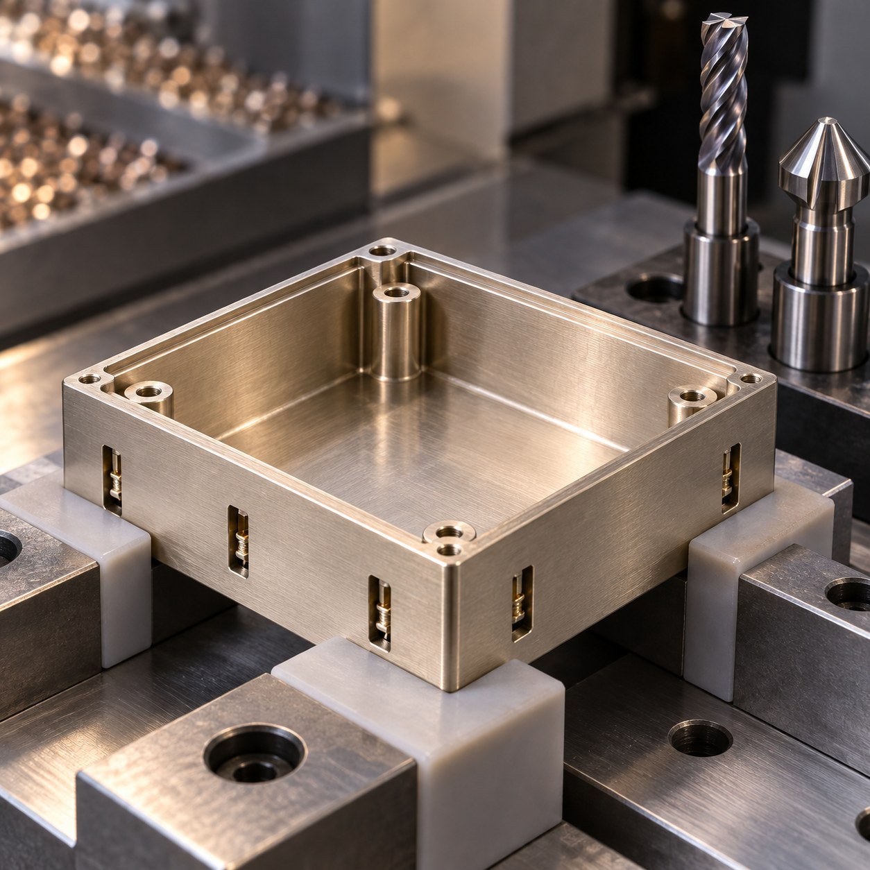
English: C77000 EMI Frame Tooling for Lid Rabbet and Contact Slots
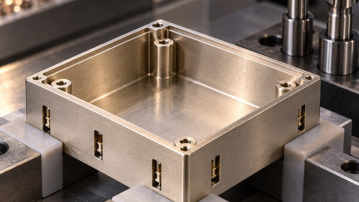
On a C77000 nickel-silver EMI enclosure frame, the lid rabbet establishes the mating gap while narrow wall slots locate separate spring contacts. The metal is chosen as a hypothetical drawing material; shielding effectiveness and contact resistance must be established by system tests, not assumed from its name. Datum A is the mounting face and B is one outside wall. Illustrative callouts are 0.04 mm rabbet depth variation and a 0.06 mm slot-position band. Burrs on the contact edges matter as much as the nominal dimensions.
Start from the lid fit, not the pocket volume
Support the continuous bottom face on a vacuum fixture or soft nest and locate the outside wall against B. Rough the center pocket with stock left on the rabbet, then semi-finish the ledge. Leave the spring-slot walls joined by sacrificial top stock until most pocket material has been removed. For the final slot cut, use a backing insert at breakout; finish the rabbet in the same datum setup so the lid gap is not transferred through another clamping error.
Nickel-silver chip behavior and edge life
C77000 is not free-machining brass. Keep the positive polished edge cutting and clear chips from the shallow rabbet before they are recut. A mist or flood strategy is chosen for the machine and later cleaning requirement, rather than assuming dry cutting. Inspect the microcutter after a first contact slot; increasing burr height or a polished-looking rubbed wall is an edge-wear signal. Do not brush a spring slot toward its mating surface.
Rabbets, slots and bosses need different cutters
| Drawing element | Carbide tool | Tradeoff at the contact edge |
|---|---|---|
| Open center pocket | 8 mm two-flute polished uncoated carbide end mill, high positive rake, rigid hydraulic holder | Adaptive roughing leaves the wall supported; a many-flute steel rougher makes sticky chips and burrs. |
| Lid rabbet and mating ledge | 3 mm two-flute polished carbide finisher, short flutes, low-runout shrink holder | Semi-finish then one light climb pass; a large end mill cannot resolve the corner relief. |
| Spring-contact slots | 1.2 mm two-flute polished carbide micro end mill, relieved neck and only required wall reach | Two shallow passes and supported exit; a long 0.6 mm cutter deflects and changes slot width. |
| Corner bosses and screw holes | 4 mm carbide spotface cutter, 2.2 mm two-flute carbide drill, short holder | Spotface from A then drill with backing; a combined drill-chamfer tool may chatter on interrupted bosses. |
| Grounding edge break | 45° single-flute sharp carbide chamfer mill with controlled offset | A narrow measured break preserves contact area; hand file can roll a conductive lip. |
Inspect the interface as an assembly
Measure rabbet depth at several points from A, slot position from B, boss height and screw-hole position after release. Use vision to check slot mouths and a soft probe or controlled gauge for the lid gap. Inspect all grounding edges for rolled burrs under magnification; document the drawing's specified roughness on the ledge. A representative lid and spring insert verify mechanical seating, while EMI performance and electrical continuity require separate tests.
Workshop FAQ
Why is a polished two-flute tool used?
It provides chip space and a sharp edge for narrow copper-alloy walls.
Can the slots be deburred by brushing?
Only with a controlled direction and acceptance check; uncontrolled brushing can roll the contact edge.
Does a tight lid gap prove shielding?
No. The assembled enclosure needs its own electrical and EMI validation.
Related tooling decisions: Molybdenum-Copper RF Heat Spreader Lid CNC Tool Selection for Gasket Moat and Vent Slots; 7075-T651 Waveguide Filter CNC Tooling Case: Thin Iris Walls and Cavity Corners.