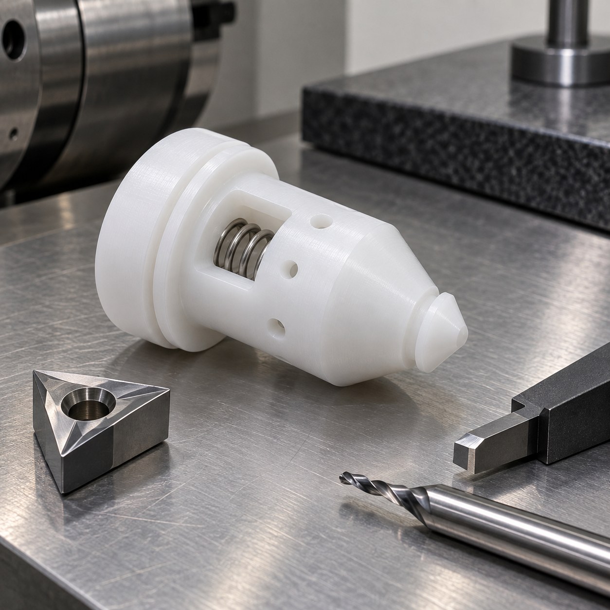
English: PCTFE Valve Poppet Tooling for Seal Cone and Spring Pocket
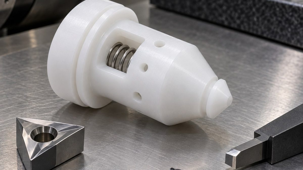
For a PCTFE cryogenic valve poppet, the cutter decision is driven by the seal cone and its relationship to the spring pocket. In this hypothetical drawing, the cone has a 30° included angle and a 0.8 mm minimum lip; the blind pocket must stay concentric within 0.04 mm to datum A, the turned body. These are illustrative targets, not a released production specification. A sharp edge and very light finish cut matter more than an aggressive removal rate.
Datum chain before cutting the lip
Grip a sacrificial stock land in a soft collet and rough the outer cylinder, shoulder and cone in one chucking. Open the spring pocket while the lip is still supported by surrounding stock, leaving a small finishing allowance on the cone and bore. A second soft-jaw setup locates from the finished body, not from the narrow lip; the radial holes then enter from a supported surface.
Feature-to-tool decisions for the cryogenic seal
| Feature on the print | carbide package | reason and rejected option |
|---|---|---|
| Body and rough cone | Polished uncoated carbide turning insert, positive rake, sharp edge; short rigid shank | Rough in shallow passes. A honed negative-rake steel insert pushes the polymer lip. |
| Final seal cone and lip | Ground positive-rake carbide form insert with a small nose radius; precision collet spindle | One continuous finishing pass avoids witness steps. A large-radius insert smears the narrow lip. |
| Blind spring pocket | 4 mm two-flute polished uncoated carbide end mill, short reach, then small boring bar | Helical roughing leaves a wall allowance; boring corrects the pocket axis. A twist drill alone leaves a poor blind floor. |
| Radial equalization holes | 1.2 mm sharp carbide microdrill, two flutes, supported exit, peck only as needed | Clean breakthrough prevents hanging polymer whiskers; a long flexible drill wanders. |
| Capture groove and edge break | 1 mm polished carbide grooving insert; 45° single-flute chamfer mill | Controlled groove width and a tiny edge break preserve snap retention; hand deburring can round the seal. |
Heat, chips and life of the sharp edge
Use dry filtered air or a coolant verified compatible with the specified PCTFE grade. Keep engagement and rubbing low, clear stringy chips before they wrap the grooving tool, and change the insert when the cone starts to haze or forms a continuous feather burr. Avoid hot hand polishing: it changes the line-contact geometry and hides the cause of a worn edge.
Release and verify the functional surfaces
After unclamping and temperature equilibration, use a noncontact profile check for cone angle and lip continuity, a bore gauge for pocket size and an optical check of each radial exit. Check groove width with a narrow gauge and compare the body-to-pocket runout on the drawing datum. Do not infer cold leak performance from room-temperature dimensions alone; any cold functional test needs its own specified procedure.
Tooling questions
Should the cone be polished after turning?
Only if a controlled allowance and method are specified; first tune the sharp finish insert and feed.
Why finish the pocket before the cone?
The pocket cut changes local support, so cone finishing belongs after its rough removal.
Can a conventional tap replace the groove tool?
No. The capture groove and a thread have different retention geometry.
Related drawing-based tooling: 6061-T6 Optical Dovetail Translation Stage CNC Tool Selection for Slide Rail and Adjustment Slots; UHMWPE Conveyor Chain Wear Guide Rail CNC Tool Selection for Curved Pocket and T-Slot Mounting Groove.