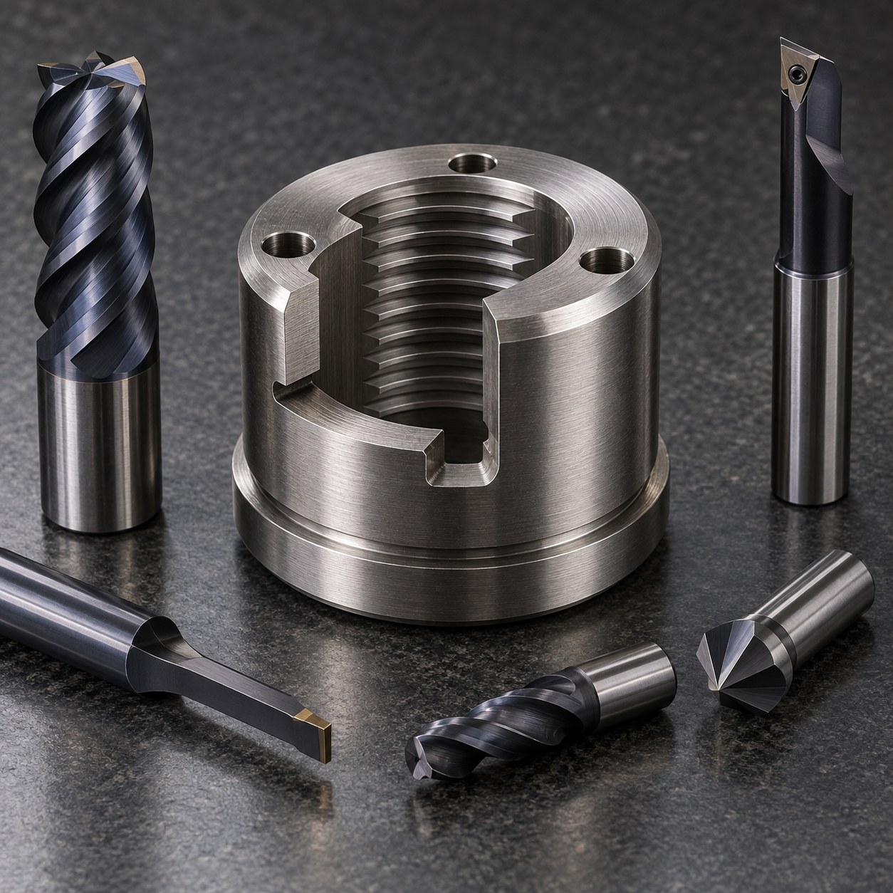
English: 13-8Mo Release Nut Tooling for Buttress Thread and Fuse Slot
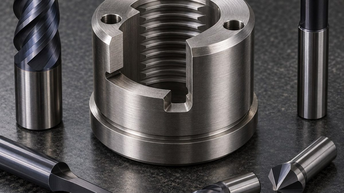
The tooling problem is to keep the load flank of an internal buttress thread concentric to the locating shoulder after a transverse fuse slot interrupts the ring. The hypothetical drawing defines the shoulder axis as datum A, the seating face as B and one wrench hole as clocking datum C; the slot is dimensioned from C, not from an arbitrary chuck jaw.
Resolve the load path and angular datum
Rough-turn the blank and bore before the specified aging treatment, leaving balanced stock on A and B. After hardness confirmation, finish the shoulder, face and bore in one chucking; thread from the deepest groove outward with constant flank engagement. Drill and clock the wrench holes while the ring is intact, machine the retaining groove, then mill the transverse fuse slot in alternating shallow passes on a split support sleeve.
Select tools before the ring is interrupted
Aged 13-8Mo can notch a cutting edge at shoulders and interrupted slot exits. Keep the thread insert below its thermal limit, avoid dwell at the load flank and monitor pitch-diameter trend rather than correcting every pass. Replace the slot mill at the first asymmetric burr or rising spindle load because a chipped micro tool can propagate a crack from the designed fuse feature.
Manage aged-steel edge damage
| Drawing feature | Carbide tool and holder | Why selected / alternative rejected |
|---|---|---|
| Locating shoulder and seating face | CNMG roughing insert then positive PVD carbide wiper insert, rigid capto holder | Roughing and finishing grades separate interrupted scale from final geometry; one universal insert risks notch wear. |
| Internal bore and buttress thread | Short anti-vibration boring bar plus full-profile PVD carbide buttress threading insert | Full profile controls crest and load flank; a tap would require high torque and cannot correct concentricity. |
| Transverse fuse slot | 2 mm 4-flute variable-helix AlTiN carbide end mill, shrink holder, radial entry | Small radial engagement limits spring-open distortion; a slitting saw overloads the interrupted ring. |
| Radial wrench holes | 3 mm through-coolant carbide drill after 5 mm carbide spot-face mill | A normal entry pad prevents drill walk; drilling directly on the diameter shifts angular relation. |
| Retaining groove and edge breaks | 1.2 mm PVD carbide grooving insert plus 45-degree carbide chamfer tool | Dedicated width controls groove floor and radius; hand grinding can nick the thread lead. |
Measure the free ring without restraint
Check shoulder runout, seating-face squareness and buttress pitch diameter before cutting the fuse slot. After slotting, measure free-state opening, thread lead and radial-hole clocking without forcing the ring closed. Use optical inspection on the slot roots and fluorescent penetrant only if the hypothetical qualification route specifies it. Release load, fracture behavior and aerospace acceptance require dedicated testing.
Practical tooling FAQ
Why cut the fuse slot after threading?
The intact ring supports a stable thread circle; slotting first would let cutting force open and close the bore.
Why use a full-profile buttress insert?
It controls the crest and designed load flank together while preserving the specified asymmetric thread form.
maraging latch heat-treatment tooling · Rene 41 interrupted-pocket tooling