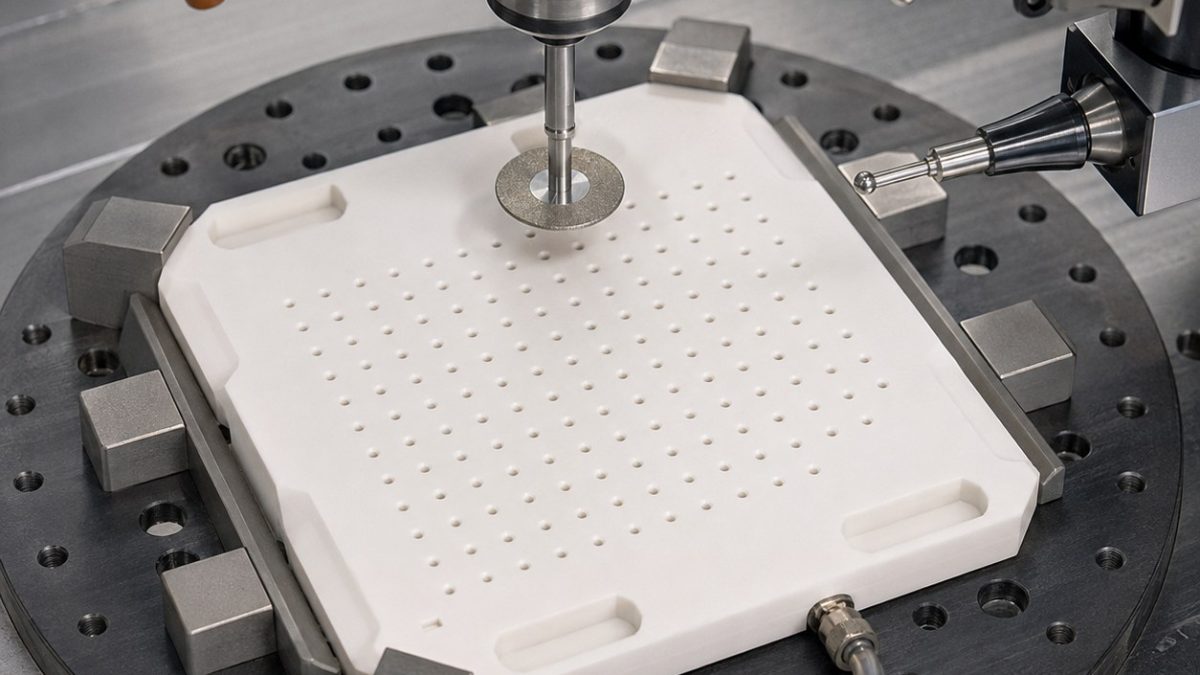
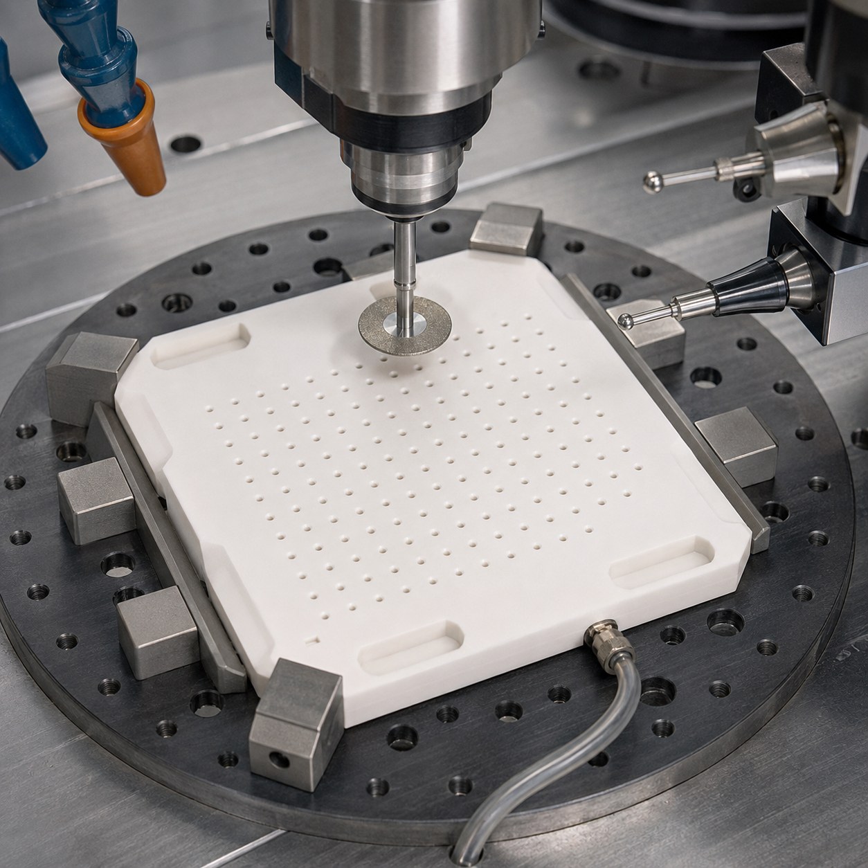
Related drawing references: ETFE Diaphragm Support CNC Tool Selection for Spiral Flexure and Raised Sealing Bead and Rene 41 Turbine Seal Segment CNC Tool Selection for Honeycomb Pocket and Feather Edges.
English: 96% Alumina Ceramic Nozzle Plate Tooling for Micro Orifices and Inlet Pockets
The search intent is narrow: how to tool an alumina nozzle plate without breaking the micro holes or losing the pocket datum. The drawing is read as a brittle-edge control problem, so grinding force, entry support and inspection coupons matter as much as nominal diameter.
Feature-to-tool selection from the drawing
| Drawing feature | Selected tool and holder | Tooling reason and rejected option |
|---|---|---|
| Ground reference face | Resin-bond diamond cup wheel, fine grit, flood-cooled fixture | Establishes flat datum with low edge chipping; a carbide face mill is rejected. |
| Micro orifice array | Ultrasonic-assisted diamond core drill, 0.45 mm, short guide bushing | Reduces breakout and lateral wander instead of forcing a conventional drill. |
| Shallow inlet pockets | Electroplated diamond pencil tool, small step-down, rigid spindle | Grinds brittle pocket corners without side loading a long burr. |
| Datum lugs | Fine-grit diamond wheel with dressed corner radius | Keeps lug repeatability while avoiding sharp-corner crack initiation. |
| Edge chamfers | Diamond chamfer pin, constant low force | Removes chips at the rim without hand stoning the functional face. |
Process order, roughing and finishing
Start by grinding the reference face on wax-backed support, then probe the lugs before any holes are opened. Orifices are drilled from the protected face with ultrasonic assistance, pockets are ground after flow direction is confirmed, and final chamfers are made only after a witness coupon proves breakout size.
Material risk, chips and tool life
Alumina does not forgive rubbing. Use low force, constant coolant and dressed diamond tools; stop when edge breakout grows on the witness coupon. Slurry must be filtered before it returns to the orifice area, and the operator should not chase size by increasing feed pressure.
Tolerance, finish and inspection plan
Inspect the datum face flatness, lug relation, orifice diameter, entry chip size and air-flow balance. Use optical measurement for each array zone, flow testing for the completed plate and a microscope check at the last chamfer pass.
FAQ for this tooling case
Why not mill alumina with ordinary carbide?
The edge pressure and heat are wrong for a brittle ceramic; diamond grinding and ultrasonic drilling reduce subsurface cracks.
When is the diamond tool dressed?
Dress before the first datum pass and again when witness-coupon breakout grows or spindle load rises.
How is nozzle performance confirmed?
Diameter is checked optically, but final release also needs flow balance because a tiny chip can change the jet.
For the drill, holder, exit-support and burr-control decision behind this feature, use the Micro-hole decision hub.


