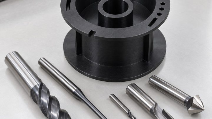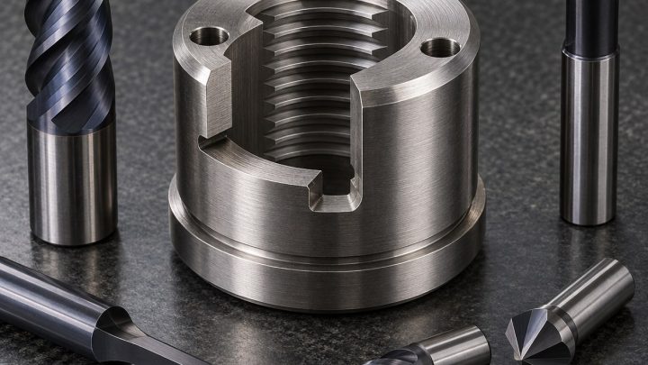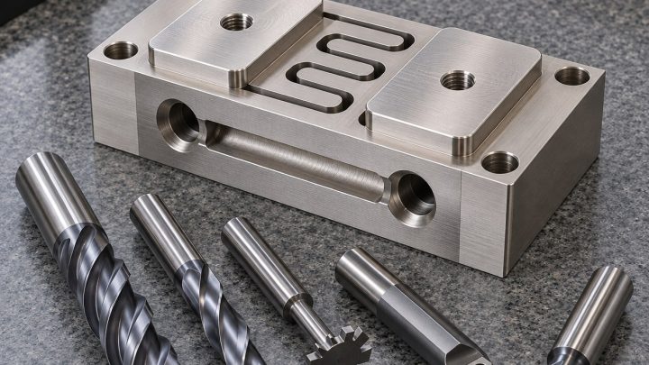

English: 440C Encoder Disc Tooling for Radial Windows and Datum Bore
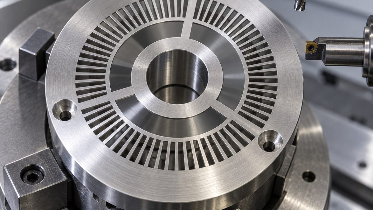
The difficult question in a 440C encoder disc is how to cut repeated radial windows without changing their pitch after the disc is released. Consider a hypothetical 52 HRC blank with a radial window array, a hub bore datum A, and thin spokes between openings. The drawing calls for window pitch error within 0.05 mm at the measurement radius and a 0.03 mm bore-to-pattern runout. Those values are illustrative. Plan the fixture and the microcutter as one system.
Clamp the disc before indexing windows
Machine datum faces and rough the bore before hardening if the route permits; after hardening, skim the reference face and fine-bore A. Seat the ring on a relieved mandrel with distributed face support so the spokes do not act as clamps. Alternate windows around the circle rather than clearing adjacent openings in sequence. Rough all windows, release and remeasure, then finish their flanks using bore A as the rotary reference.
Control tool life at each interruption
Hard 440C produces concentrated heat and abrasive wear at each window entry. Use a stable low-radial-engagement path and consistent coolant delivery qualified for the machine; avoid rubbing at a nearly zero chip load. Record flank wear under magnification and use a reference window at the start and end of a tool life interval. A suddenly widening kerf or burr at the exit is a change-tool signal, not a reason to force more passes.
A cutter for each encoder feature
| Functional detail | chosen cutter | tradeoff |
|---|---|---|
| Hub bore datum A | Coated carbide pilot and small fine-boring bar, short balanced holder | Boring after rough stress relief sets the true rotation center; an as-drilled hole is not the datum. |
| Window bulk removal | 2 mm four-flute AlTiN carbide micro end mill with reinforced core, 6 mm reach | Adaptive shallow engagement reduces edge load; full-width slotting overheats the tiny cutter. |
| Window flank finish | 1 mm two-flute TiSiN carbide micro end mill, slight edge hone, shrink holder | Two flutes leave chip space and a small stock allowance; a blunt abrasive burr rounds the optical edges. |
| Three mounting counterbores | Coated carbide spot drill, 2.5 mm drill, then 5 mm counterbore with pilot | Staged holemaking limits exit burr and keeps bolt seats square. |
| Spoke corner relief | 0.6 mm neck-relieved two-flute carbide radius mill, minimum projection | Matches the drawn root radius; a sharp internal corner would invite cracking. |
Measure the pattern in its free state
Inspect hardness before choosing the coated grade. After unclamping, measure bore roundness and face flatness, then use an optical comparator or vision system to calculate angular pitch from the bore center. Inspect window width at the specified radius and root radii at spoke ends. Treat any burr that affects the optical edge as a dimensional defect; do not hand-stone the pattern without a controlled allowance.
Tooling questions
Why not cut every window in one full slot?
Full engagement overloads the small carbide tool and concentrates heat at the spokes.
Should the bore be final before the windows?
Establish its final reference before the final indexing passes, then verify it after release.
Does a good CMM pitch result prove optical function?
No. Edge quality and the sensor's own acceptance check remain separate.
Related drawing-based tooling: Inconel 718 Turbine Oil Nozzle Ring CNC Tool Selection for Angled Jet Holes and Scalloped Pockets; AZ31B Magnesium Camera Heat Sink Housing CNC Tool Selection for Thin Cooling Fins and Lens Boss Pocket.