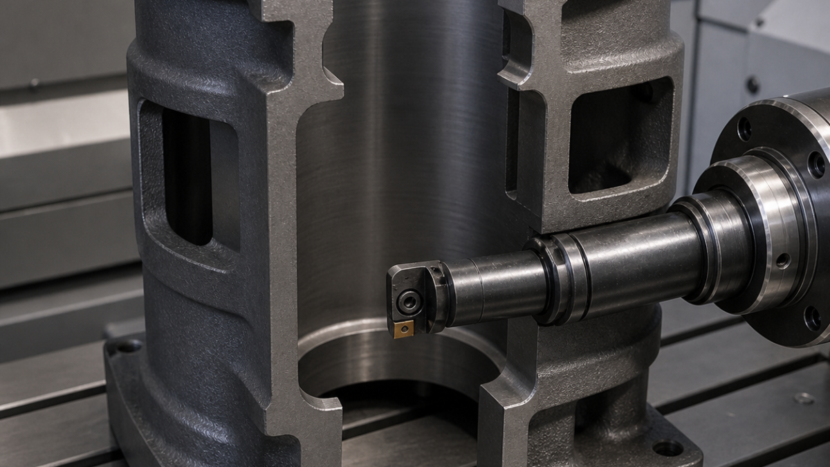
English: EN-GJL-250 Compressor Cylinder Liner CNC Tool Selection for Port Windows and Honing Stock
The correct tooling plan for an EN-GJL-250 compressor cylinder liner starts by protecting the honing stock, not by chasing a finished bore on the machining center. This hypothetical drawing calls for an interrupted port belt, a controlled Ø86 bore with 0.030 mm radial honing allowance, a flange face related to that bore, and burr-free port edges. Short ISO-K carbide boring inserts, a damped semifinish bar, cast-iron slot mills and a reverse-edge tool keep those requirements in one measurable datum chain.
What the hone must inherit
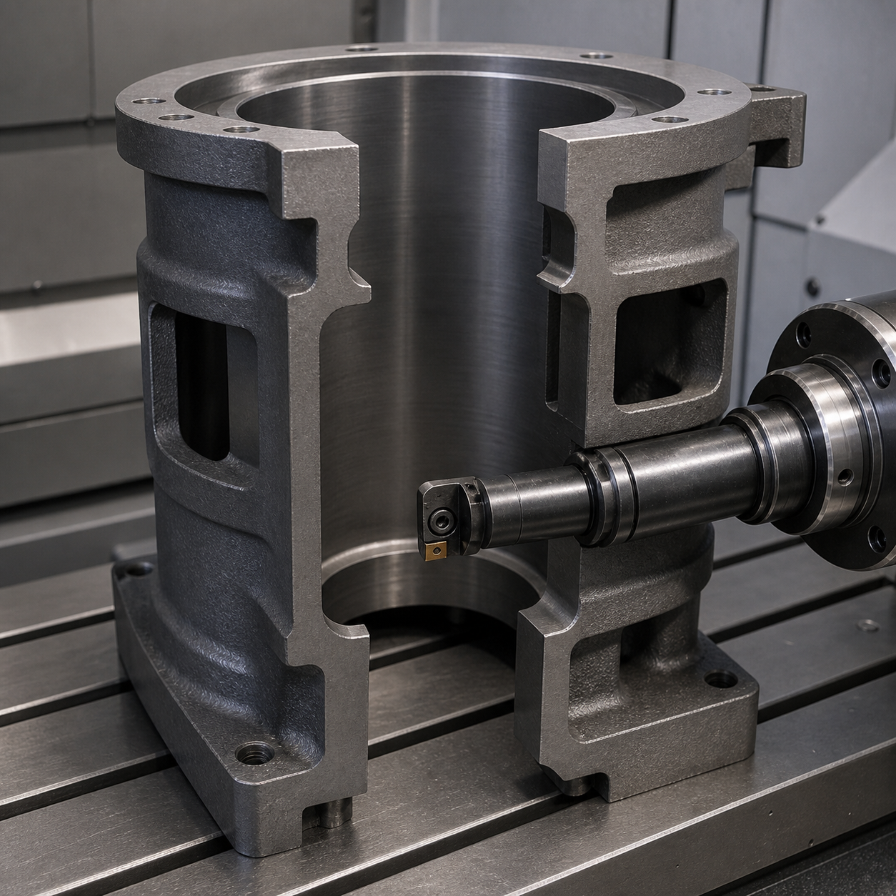
Flange face A locates the liner axially; bore B establishes the working axis; one wide inlet window defines clock datum C. The pre-hone bore is Ø85.940–85.955 mm with cylindricity 0.018 mm, leaving 0.022–0.030 mm radial stock for a final Ø86 H6 plateau-honed surface. Six rectangular windows cross the wall at 60° intervals, with top edges 42.00 ±0.03 mm from A and angular position ±0.08°. The upper counterbore is Ø92 H7, flange runout to B is 0.020 mm, and a 1.20 mm oil groove must not blend into a port corner.
This makes the port belt an interrupted-bore problem. Cutting all windows first weakens the wall before the semifinish bore; finishing the bore first lets window breakouts damage the honing stock. The route therefore roughs both systems, stabilizes the liner, then alternates bore and window finishing around a defined inspection gate.
Tool decisions at each handoff
| Feature and stage | Carbide tool, grade, geometry and holder | Reason and alternative rejected |
|---|---|---|
| Raw flange and OD roughing | CNMG 120408 ISO-K20 CVD TiCN/Al2O3 carbide, medium-positive chipformer, 0.8 mm nose radius, rigid capto holder | The wear-resistant K grade tolerates the cast skin. A sharp aluminium insert chips on sand inclusions. |
| Bore roughing before ports | Ø63 four-edge rough-boring head with ISO-K15 coated carbide cartridges, R0.8, 0° lead, short modular bar | Balanced cartridges remove stock without forcing one long insert bar; high lead would push the slender wall radially. |
| Window opening and corners | Ø12 five-flute fine-grain carbide end mill, AlCrN, 38° variable helix, R0.5, 22 mm reach in a power-shrink holder; Ø6 four-flute R0.3 rest tool | Five flutes suit dry cast-iron chips and distribute the interrupted load. A two-flute aluminium mill has weak support at the window entry. |
| Bore semifinish to honing stock | Positive CCMT 060204 ISO-K10 carbide with CVD wear layer and light T-land, R0.4, internal-air damped bar at 4.5×D reach | The damped bar holds cylindricity after ports exist. PCBN is rejected here because repeated port impacts make edge cost and fracture risk unnecessary at the required pre-hone finish. |
| Ø92 H7 counterbore | Adjustable twin-edge fine-boring head, ISO-K10 carbide, wiper-flat insert, HSK-A100 short adapter | Diameter can be corrected independently of B while the wiper stabilizes Ra 1.6 µm. |
| 1.20 mm internal oil groove | 1.20 mm full-radius PVD-TiAlN carbide grooving insert on a short anti-vibration bar, neutral rake | Neutral radial load prevents groove taper. A form tool that also cuts the port chamfer would be too wide and prone to chatter. |
| Port back edges | Ø10 replaceable-head carbide reverse chamfer tool, four teeth, 45°, AlCrN, through-air holder | It breaks the internal window edge under program control; hand grinding risks scratching the honing allowance. |
| Bolt circle and flange chamfer | Ø6 three-flute ISO-K carbide drill, 140° point; Ø12 six-flute 90° carbide chamfer mill | The drill handles graphite-rich chips; a combined drill-chamfer would tie hole depth wear to the sealing-face edge. |
A route built around the interrupted cut
Operation 10 grips the casting on three qualified OD pads and faces A, turns the flange pilot, and rough-bores B with 0.40 mm radial stock. A light clamp ring replaces hard jaw pressure before the windows are opened. Each port is ramped from its centre, roughed with constant radial engagement, and left 0.08 mm on walls and 0.05 mm at the top edge. Opposite windows are paired so the liner releases symmetrically.
After a thermal pause, the damped bar semifinishes B in two passes: the first reveals interrupted-load variation; the second creates uniform honing stock. The port rest tool then brings C and the remaining windows to position without touching the protected bore. Dry extraction is preferred for loose graphite dust where the machine and risk assessment permit it; otherwise the validated coolant and filtration plan must prevent abrasive recirculation. Flank wear, chipped T-land, a periodic load peak at every window or a lobed bore trace ends the tool’s service.
Inspection handed to honing
An air gauge samples B at three heights and two angular orientations; a roundness instrument distinguishes six-lobe clamp error from taper. A CMM builds A-B-C, measures window height and angle, and checks flange runout. Replica tape or optical inspection confirms the reverse chamfers without touching the bore. Only after cylindricity and minimum honing stock are accepted does plateau honing begin. Final size, cross-hatch, Ra/Rpk/Rvk and cleanliness belong to the validated honing specification, not to unsupported claims in this hypothetical case.
How much machining stock should remain before cylinder-liner honing?
This drawing uses 0.022–0.030 mm radially. The actual allowance must exceed the measured pre-hone form error while staying within the hone’s removal capability.
Which carbide grade suits gray-cast-iron port windows?
A wear-resistant ISO-K fine-grain carbide with an AlCrN or proven cast-iron coating and a supported corner handles the interrupted entry better than a sharp, low-support aluminium geometry.
Why deburr the port from inside with a reverse tool?
The programmed back chamfer removes the breakout lip without dragging an abrasive across the precision bore or consuming uneven honing stock.
Related cases: cast-iron bore and face tooling and controlled carbide chamfering.
中文: EN-GJL-250压缩机缸套配刀:气口窗口与珩磨余量
EN-GJL-250压缩机缸套的配刀起点不是在加工中心上直接追求最终孔径,而是给珩磨留下均匀、可测的余量。本假想图纸包含中断气口带、带0.030 mm径向余量的Ø86孔、与孔轴关联的法兰面及无毛刺窗口。短悬伸ISO-K硬质合金镗刀、减振半精镗杆、铸铁窗口铣刀和反向倒角刀把这些要求串在同一基准链内。
珩磨工序真正要接收什么
法兰A定轴向,内孔B定工作轴,一处加宽进气窗为角向基准C。珩前孔Ø85.940–85.955 mm,圆柱度0.018 mm,为最终Ø86 H6平台珩磨保留0.022–0.030 mm径向余量。六个矩形气口按60°分布,上沿距A为42.00 ±0.03 mm,角位置±0.08°。上止口Ø92 H7,法兰对B跳动0.020 mm,1.20 mm油槽不能与气口圆角相交。
气口带使内孔成为断续切削。先把窗口全部精完会削弱缸壁,先精孔又会让窗口突破损伤珩磨余量。因此路线先让两套特征共同开粗,稳定后再围绕检验门交替完成半精孔和窗口。
工序交接处的配刀表
| 特征与阶段 | 硬质合金牌号、几何及刀柄 | 理由与排除方案 |
|---|---|---|
| 毛坯法兰和外圆 | CNMG 120408,ISO-K20,CVD TiCN/Al2O3,中正前角槽型,R0.8,Capto刚性柄 | K类耐磨牌号承受铸造皮;锋利铝用片遇砂粒会崩刃。 |
| 开窗口前粗镗B | Ø63四刃粗镗头,ISO-K15涂层硬质合金刀夹,R0.8,0°主偏,短模块杆 | 平衡切削减少单杆挠曲,高主偏角会增大薄壁径向推力。 |
| 气口窗口及圆角 | Ø12五刃细晶硬质合金,AlCrN,38°变螺旋、R0.5、刃长22 mm,强力热缩柄;Ø6四刃R0.3清根刀 | 五刃分担断续冲击并适合铸铁碎屑;两刃铝刀入口支承不足。 |
| 带余量半精镗B | CCMT 060204正角ISO-K10硬质合金,CVD耐磨层、轻T刃、R0.4,4.5×D内通气减振杆 | 开窗后仍保持圆柱度;PCBN在多次气口冲击下成本和崩刃风险都无必要。 |
| Ø92 H7止口 | 可调双刃精镗头,ISO-K10硬质合金,修光刃,HSK-A100短接杆 | 尺寸可独立补偿,修光刃稳定Ra 1.6 µm。 |
| 1.20 mm内油槽 | 1.20 mm全圆弧PVD-TiAlN硬质合金槽刀,短减振杆,中性前角 | 中性径向力抑制槽宽锥度;同时兼作窗口倒角的宽成形刀会颤振。 |
| 窗口内侧边 | Ø10四齿可换头45°AlCrN硬质合金反向倒角刀,通气刀柄 | 程序控制内缘倒角,拒绝会划伤珩磨余量的手工砂磨。 |
| 螺栓圈和法兰倒角 | Ø6三刃ISO-K硬质合金钻,140°钻尖;Ø12六刃90°硬质合金倒角刀 | 钻头处理含石墨碎屑;分刀避免孔深磨损影响密封面倒角。 |
围绕断续切削安排路线
第一装夹用三处合格外圆垫定位,完成A面、法兰止口并将B粗镗至留0.40 mm径向余量。开窗前用轻载环夹替换硬爪压力。窗口从中心螺旋进入,以恒定径向吃刀开粗,壁留0.08 mm、上沿留0.05 mm;对置窗口成对完成,使缸套对称释放。
恒温后减振杆分两刀半精B:首刀暴露各窗口的断续负载,第二刀形成均匀珩磨余量。Ø6清根刀再修C和其余气口,禁止擦到已保护内孔。若机床和风险评估允许,可用干式抽吸处理石墨粉;否则切削液与过滤必须经过验证,不能让磨粒循环。后刀面磨损、T刃崩角、每遇窗口周期性负载峰或孔形六瓣化都触发换刀。
交给珩磨前的检验
气动量仪在三高度、两角向测B,圆度仪区分夹紧六瓣与锥度;三坐标建立A-B-C,测窗口高度、角度和法兰跳动。复制胶或光学方法检查反向倒角而不触碰内孔。只有圆柱度和最小余量合格后才进入平台珩磨;最终Ra、Rpk、Rvk、网纹和清洁度应由正式珩磨规范定义。
缸套珩磨前应留多少加工余量?
本图纸径向留0.022–0.030 mm;实际值要大于实测孔形误差,同时不超出珩磨去除能力。
灰铸铁气口窗口用什么硬质合金?
选耐磨ISO-K细晶基体、AlCrN或已验证铸铁涂层并带有支承圆角的刀,抗断续入口能力优于薄刃铝用几何。
为什么从内侧用反向刀去毛刺?
它按程序去除突破唇边,不用砂料拖过精密孔,也不会不均匀消耗珩磨余量。
Français: Outils pour chemise EN-GJL-250 : lumières et surépaisseur de rodage
La gamme d’une chemise de compresseur EN-GJL-250 doit d’abord fournir une surépaisseur de rodage régulière. L’alésage interrompu par six lumières, la face de bride et les arêtes internes sont traités avec des carbures ISO-K courts, une barre amortie et un outil de chanfrein arrière.
État remis au rodage
A fixe l’axe, B est l’alésage, et la large lumière C indexe l’angle. Avant rodage, B vaut Ø85,940–85,955 mm avec cylindricité 0,018 mm; il reste 0,022–0,030 mm radial pour Ø86 H6. Six fenêtres sont à 60°, leurs sommets à 42,00 ±0,03 mm de A et leur angle à ±0,08°. Le lamage supérieur est Ø92 H7 et la rainure d’huile mesure 1,20 mm.
Finir toutes les lumières affaiblirait la paroi avant B; finir B en premier exposerait sa réserve aux débouchés. La gamme ébauche les deux systèmes puis alterne les finitions après stabilisation.
Table des outils aux interfaces
| Étape | Carbure et montage | Décision |
|---|---|---|
| Bride brute | CNMG 120408 ISO-K20 CVD TiCN/Al2O3, géométrie semi-positive, R0,8, Capto | Résiste à la peau moulée; une plaquette aluminium s’ébrèche. |
| Ébauche B | Tête Ø63 à quatre cartouches K15, R0,8, angle 0°, barre courte | Coupe équilibrée et faible poussée radiale. |
| Lumières | Ø12, cinq dents, AlCrN, hélice variable 38°, R0,5, portée 22 mm; reprise Ø6 R0,3 | Dents soutenues pour l’entrée interrompue. |
| Semi-finition B | CCMT 060204 K10 CVD, léger T-land, R0,4, barre amortie 4,5×D | Tient la cylindricité; le PCBN n’est pas justifié aux chocs. |
| Ø92 H7 | Tête d’alésage à deux arêtes, K10, plan wiper, adaptateur court HSK-A100 | Réglage indépendant et Ra 1,6 µm. |
| Rainure 1,20 | Insert carbure TiAlN plein rayon, barre courte, coupe neutre | Évite la conicité de largeur. |
| Arêtes internes | Tête carbure AlCrN Ø10, quatre dents, 45°, coupe arrière | Pas d’abrasif sur la réserve d’alésage. |
| Trous et chanfrein | Foret K Ø6 à trois lèvres, 140°; chanfreineuse Ø12 à six dents, 90° | Fonctions séparées et copeau graphite maîtrisé. |
Ordre opposé et signature d’usure
A et B sont ébauchés avec 0,40 mm radial. Une bague légère remplace les mors avant les lumières, usinées par paires opposées et engagement constant. Après pause thermique, deux passes de la barre amortie créent la réserve. La charge périodique, un T-land écaillé ou une trace lobée retire l’outil.
L’extraction à sec n’est employée que si machine et évaluation le permettent; sinon la filtration validée empêche la recirculation des particules abrasives.
Mesure avant rodage et FAQ
Une jauge pneumatique mesure B à trois hauteurs; le rondimètre sépare serrage à six lobes et conicité. La MMT reconstruit A-B-C et l’optique vérifie les chanfreins. Le rodage ne commence qu’après acceptation de la réserve minimale.
Quelle surépaisseur avant rodage?
Ici 0,022–0,030 mm au rayon, à adapter à la forme mesurée et à la capacité du procédé.
Quel carbure pour les lumières?
Un ISO-K à angle soutenu et revêtement AlCrN validé pour la fonte.
Pourquoi un outil arrière?
Il enlève la lèvre interne sans rayer l’alésage réservé.
Voir l’usinage des alésages en fonte et le chanfreinage carbure.
Русский: Инструмент для гильзы EN-GJL-250 и окон
Для компрессорной гильзы EN-GJL-250 важно передать хонингованию равномерный припуск. Прерывистое отверстие с окнами, фланец и внутренние кромки обрабатываются короткими карбидами ISO-K, демпфированной оправкой и обратной фасочной головкой.
Что получает хонингование
A задаёт ось, B — отверстие, широкое окно C — угол. До хонингования B равно Ø85,940–85,955 мм при цилиндричности 0,018 мм; радиальный припуск 0,022–0,030 мм оставлен под Ø86 H6. Шесть окон расположены через 60°, верх на 42,00 ±0,03 мм от A, угол ±0,08°. Верхняя расточка Ø92 H7, масляная канавка 1,20 мм.
Если сначала закончить окна, стенка ослабнет; если закончить B, прорыв повредит припуск. Поэтому обе системы черновые, а чистовые переходы чередуются после стабилизации.
Инструмент на переходах
| Переход | Карбид и державка | Причина |
|---|---|---|
| Фланец | CNMG 120408 K20 CVD TiCN/Al2O3, среднеположительная геометрия, R0,8, Capto | Выдерживает литейную корку. |
| Черновое B | Ø63, четыре кассеты K15, R0,8, угол 0°, короткая оправка | Сбалансированная малая радиальная сила. |
| Окна | Ø12, пять зубьев, AlCrN, переменная спираль 38°, R0,5, длина 22 мм; остаточная Ø6 R0,3 | Опора кромки при прерывистом входе. |
| Получистовое B | CCMT 060204 K10 CVD, лёгкая T-фаска, R0,4, демпфированная штанга 4,5×D | Держит цилиндричность; PCBN не нужен при ударах. |
| Ø92 H7 | Двухлезвийная регулируемая головка K10 с wiper, короткий HSK-A100 | Независимая коррекция и Ra 1,6 мкм. |
| Канавка 1,20 | Полнопрофильный TiAlN-карбид, нейтральный угол, короткая штанга | Нет конусности ширины. |
| Внутренние кромки | Обратная четырёхзубая головка Ø10, AlCrN, 45° | Не царапает припуск B. |
| Отверстия | Трёхзубое сверло K Ø6, 140°; шестизубая фасочная Ø12, 90° | Раздельный контроль глубины и фаски. |
Парный порядок окон
A и B черновые с радиальным припуском 0,40 мм. Перед окнами жёсткие кулачки заменяет лёгкое кольцо; противоположные окна режутся попарно с постоянным зацеплением. После паузы две проходки демпфированной штанги создают припуск. Периодический пик нагрузки, скол T-кромки или лепестковый след завершают ресурс.
Сухое удаление графитовой пыли допустимо лишь после проверки станка и риска; иначе проверенная фильтрация должна исключить возврат абразива.
Контроль и FAQ
Пневмокалибр измеряет B на трёх высотах, кругломер отделяет шесть лепестков зажима от конуса. КИМ строит A-B-C, оптика проверяет обратные фаски. Хонингование начинается после приёмки минимального припуска.
Какой припуск оставить?
Здесь 0,022–0,030 мм на радиус, но он зависит от измеренной формы и возможности хона.
Какой карбид нужен для окон?
Износостойкий ISO-K с опорной кромкой и проверенным AlCrN.
Зачем обратная фаска?
Она снимает внутреннюю губу без абразива на точном отверстии.


