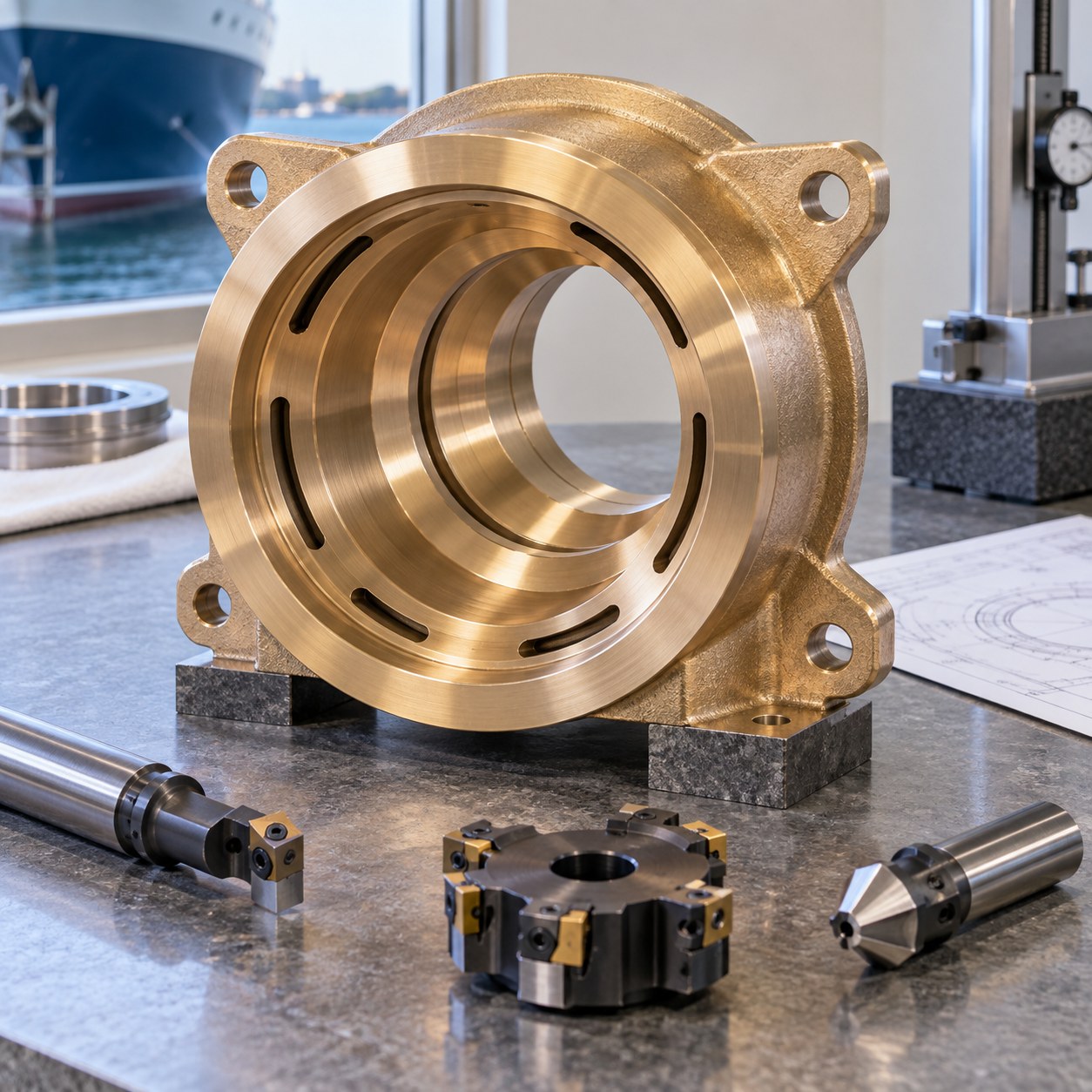
English: C65500 Seal Carrier Tooling for Stepped Bore and Water Slots
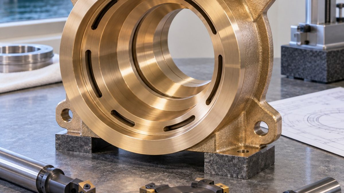
This case answers how to preserve coaxial seal lands while opening curved water slots in a C65500 carrier. The drawing is controlled by the shaft bore and two seal diameters; the cast outside and four ears only establish stock and fastening. Illustrative values do not represent a real vessel component.
Cut the coaxial stack in one grip
| Drawing feature | Carbide tool and holder | Why this choice / rejected alternative |
|---|---|---|
| Pilot shaft bore | Indexable carbide drill with polished positive insert, through coolant | Opens stock without long stringers; HSS rubbing encourages built-up edge. |
| Two seal lands | Fine boring bar with 0.2 mm polished uncoated carbide insert, rigid Capto holder | One radial reference preserves coaxiality; separate reamers can follow different axes. |
| Curved water slots | 6 mm 3-flute polished ZrN carbide end mill, variable helix, shrink holder | Trochoidal side engagement controls adhesion; full-width slotting welds chips to the edge. |
| Mounting ears | 10 mm 3-flute carbide end mill with corner radius | Corner radius protects the ear root; a square sharp cutter concentrates load. |
| Drain notch and edge breaks | 4 mm 2-flute carbide mill plus 45° single-flute chamfer cutter | Machine burr toward an accessible face; hand grinding rolls the sealing datum. |
Water-slot engagement and burr direction
Indicate the rough casting from the strongest rear pad, face it, and complete the pilot, finish bores and seal shoulders without releasing the setup. Transfer to an expanding mandrel on the finished bore, rough opposite water slots in pairs, then finish each slot with climb passes that direct the exit burr away from the seal lands.
Managing bronze adhesion
Silicon bronze can form a built-up edge that changes bore size before the tool looks worn. Use polished positive geometry, avoid dwelling at the slot exit, and watch for a matte dragged band, a sudden burr lip or rising torque. Replace or clean the edge before compensating size.
Released runout and seal-land inspection
After unclamping, measure both seal diameters, shoulder spacing and total indicated runout from the shaft bore. Use optical inspection for water-slot exits and a contour trace across the drain notch. A dummy shaft and seals may check assembly only; leakage and marine acceptance are separate.
Search-driven tooling FAQ
Why not ream both seal diameters?
Separate reamers follow existing pilots; fine boring from one setup controls their common axis.
Why machine opposite slots in pairs?
Balanced material removal reduces movement of the ring around the seal lands.
Ti-6Al-7Nb Dental Drill Guide CNC Tool Selection for Angled Sleeve Bore and Tooth Saddle · C77000 Nickel Silver EMI Frame CNC Tool Selection for Lid Rabbet and Spring Contact Slots