This is a realistic hypothetical process-planning example, not a claim about a specific customer drawing or production result.
Related: Read the related CNC tooling case.
English: Additively Manufactured AlSi10Mg Hydraulic Manifold CNC Case: Datum Bosses, Seal Faces and Port Finishing
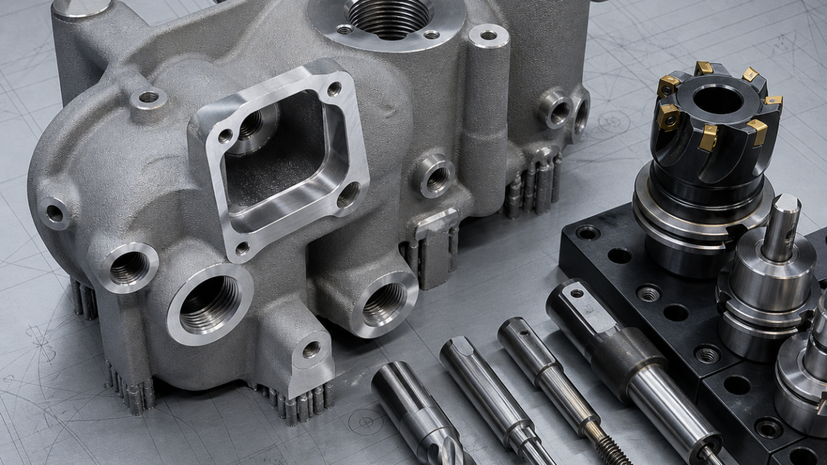
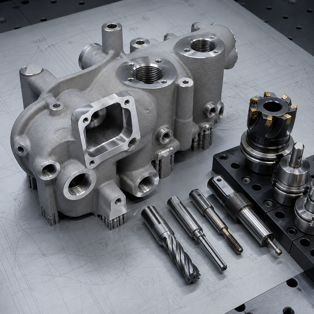
This hypothetical AlSi10Mg manifold is printed near net shape with sacrificial supports, dedicated datum bosses, curved internal passages and machining allowance on seal faces and ports. The CNC plan must reconcile the as-built scan with the nominal model before any critical stock is removed.
Feature and datum interpretation
Use three printed pads to create datum A, a reamed transfer hole for B and a second boss for clocking C. Compare the scan to nominal and verify that every sealing face and threaded port has cleanup stock. Internal passages should be treated as inspection features even when they are not directly machined.
Carbide tool selection
Use a positive-rake face mill or PCD-compatible cutter for sealing pads, sharp carbide end mills for support stubs, carbide drills and reamers for datum holes, and thread mills for ports. A back-deburring tool reaches break-through edges; low cutting force helps avoid opening subsurface porosity.
Fixture and process sequence
Remove only supports that obstruct the first fixture, then skim datum bosses and probe the full part. Finish primary seal faces and transfer holes in the most rigid orientation. Refixture through the recovered datums for ports, thread milling and controlled edge breaks, leaving nonfunctional additive surfaces untouched.
Tolerance, surface and tool-life risks
Printed variation, trapped powder, porosity and residual stress can create leaks or datum shift. Use staged probing, filtered extraction and conservative breakthrough moves. Pressure-test requirements come from the drawing or process specification; do not infer acceptance from visual finish alone. Verify thread gauges, face flatness, port position and internal burr condition.
FAQ
Why recover datums before finishing?
Because the functional geometry must be related to the actual part, not an assumed nominal center.
Why inspect after unclamping?
Clamping can temporarily hide distortion or runout.
中文: 增材制造 AlSi10Mg 液压块 CNC 案例:打印基准凸台、密封面与接口精加工
本假设 AlSi10Mg 液压块采用近净成形打印,包含牺牲支撑、专用基准凸台、弯曲内流道以及密封面和接口加工余量。关键余量去除前,必须把实物扫描结果与理论模型对齐。
特征与基准解释
以三个打印垫建立基准 A,以铰削转移孔建立 B,以第二凸台确定角向 C。将扫描数据与理论模型比较,确认每个密封面和螺纹口都有完整见光余量;即使内流道不直接加工,也应作为重要检测特征。
硬质合金刀具选择
密封台面使用正前角面铣刀或适用的 PCD 刀具,支撑残根用锋利硬质合金立铣刀,基准孔采用硬质合金钻和铰刀,接口使用螺纹铣刀。反向去毛刺刀处理贯通边缘,低切削力可降低暴露近表面孔隙的风险。
夹具与工序顺序
第一工位只去除妨碍装夹的支撑,轻铣基准凸台后全面探测工件。在刚性最好的姿态完成主要密封面和转移孔,再依据恢复后的基准重装,加工接口、螺纹和受控倒角,非功能打印表面不做无谓切削。
公差、表面与刀具寿命风险
打印偏差、残粉、孔隙和残余应力都可能引起泄漏或基准漂移。采用分阶段探测、过滤抽吸和保守贯通刀路。压力测试要求必须来自图纸或工艺规范,不能凭外观判断;还需检查螺纹量规、平面度、接口位置及内部毛刺。
常见问题
为什么精加工前要恢复基准?
功能几何必须对应实际零件,而不是假设的理论中心。
为什么卸夹后还要检测?
夹紧力可能暂时掩盖变形或跳动。
Français: Cas CNC d’un collecteur hydraulique AlSi10Mg fabriqué par additive : plots de référence, faces d’étanchéité et finition des ports
Ce collecteur hypothétique en AlSi10Mg est imprimé près de la forme finale avec supports, plots de référence, canaux courbes et surépaisseurs sur faces et ports. Le scan réel doit être aligné au modèle avant toute reprise critique.
Fonctions et références
Trois plots créent A, un trou alésé B et un second bossage C. Comparer le scan au nominal et confirmer la matière disponible sur chaque face et port.
Choix des outils carbure
Employer une fraise positive ou compatible PCD, des fraises carbure vives, forets et alésoirs, fraises à fileter et outil d’ébavurage arrière. Les efforts faibles limitent l’ouverture de porosités.
Montage et gamme
Retirer seulement les supports gênants, dresser les références et palper la pièce. Finir faces et trous de transfert dans la position la plus rigide, puis reprendre les ports depuis ces références.
Risques de qualité et d’usure
Variation d’impression, poudre, porosité et contraintes peuvent provoquer fuite ou dérive. Contrôler par étapes et vérifier filetages, planéité, position et bavures internes selon la spécification.
FAQ
Pourquoi reconstruire les références ?
La géométrie fonctionnelle doit suivre la pièce réelle.
Pourquoi contrôler après débridage ?
Le serrage peut masquer une déformation.
Русский: Коллектор AlSi10Mg: базовые бобышки, уплотнительные торцы и порты
Условный коллектор AlSi10Mg напечатан почти в размер и имеет опоры, базовые бобышки, кривые каналы и припуск на уплотнениях. Перед резанием фактический скан совмещают с моделью.
Функции и базы
Три площадки создают базу A, развернутое отверстие — B, вторая бобышка — C. Скан подтверждает припуск на каждом торце и порте.
Твердосплавный инструмент
Применяют положительную или PCD-совместимую фрезу, острые твердосплавные фрезы, сверла, развертки, резьбовые и обратные фасочные инструменты.
Установ и маршрут
Сначала удаляют мешающие опоры, создают базы и измеряют деталь. Уплотнения и переносные отверстия делают в жесткой позиции, затем по ним обрабатывают порты.
Риски точности и стойкости
Отклонения печати, порошок, поры и напряжения вызывают утечки. Нужны поэтапное измерение и контроль резьбы, плоскости, положения и внутренних заусенцев.
FAQ
Зачем восстанавливать базы?
Функциональная геометрия должна соответствовать реальной детали.
Зачем измерять после освобождения?
Зажим может скрывать деформацию.


