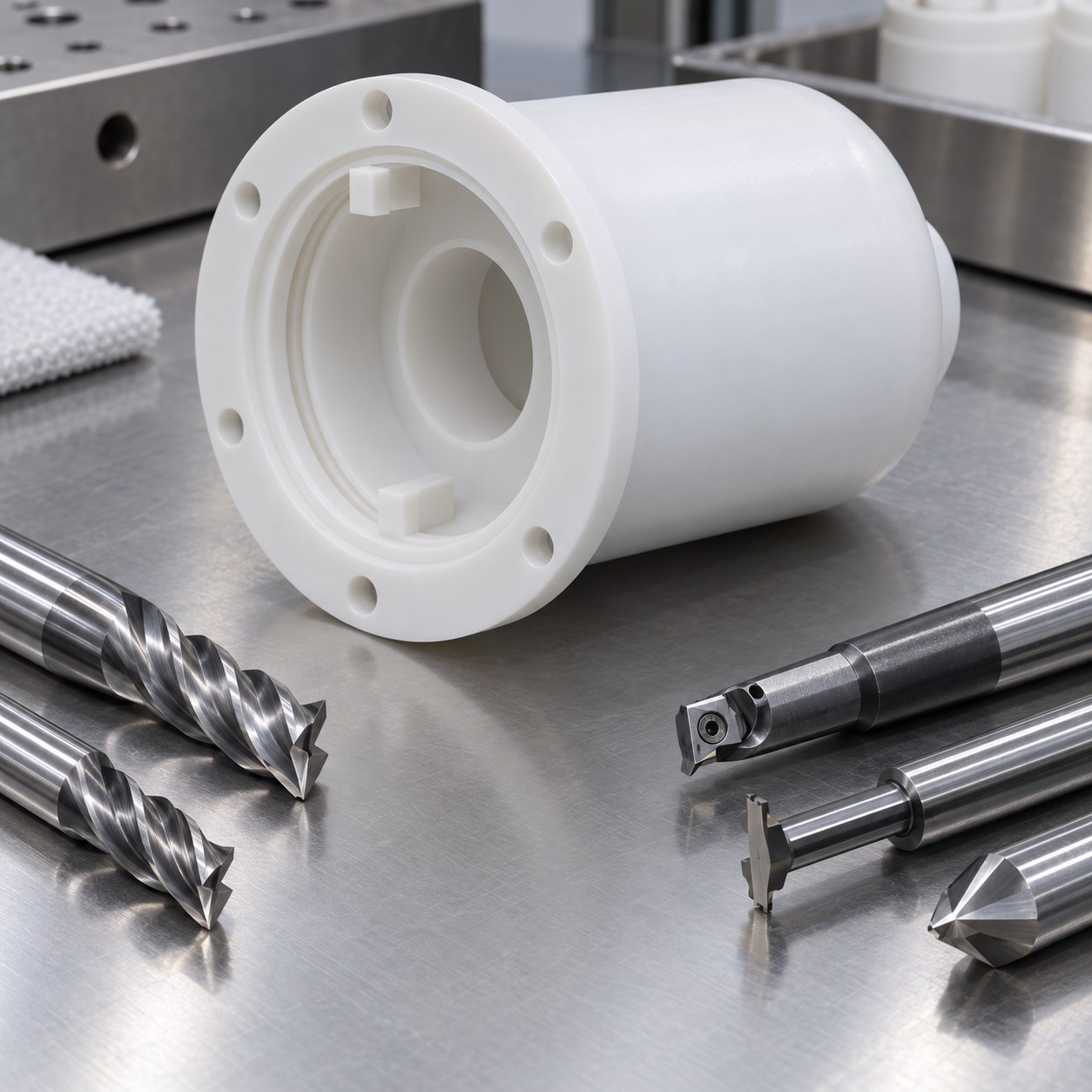
English: PVDF Pump Shell Tooling for Thin Cup Wall and O-Ring Groove
The drawing challenge is keeping a closed thin cup concentric to the flange register after most internal stock is removed. The hypothetical flange face is A and the register is B; cup wall thickness is bilateral from B, not from the raw outside. Anti-rotation tabs only clock assembly.
Read functional datums before selecting tools
Face the flange and machine tabs while the blank is thick. Helically rough the internal cup in depth bands, leaving a supporting core at the closed end. Semifinish the bore and register, rest the part for thermal recovery, then finish opposite wall sectors in alternating order on a full flange nest. Cut the O-ring groove and remove the core last.
Match each drawing feature to a cutter
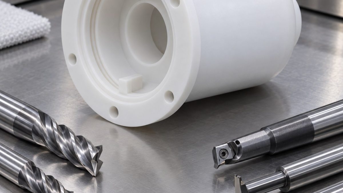
PVDF softens with heat and can pull into a dull edge. Use sharp polished tools, generous chip space and approved air or coolant. Reject the finisher when the wall becomes glossy, stringers wrap the tool or spindle load rises. Dimensional inspection must use a controlled conditioning temperature.
Control material-specific failure modes
| Drawing feature | Carbide tool and holder | Why selected / alternative rejected |
|---|---|---|
| Flange face and register | 10 mm 2-flute polished uncoated carbide end mill, hydraulic holder | Sharp edge avoids heat; a many-flute cutter traps soft chips. |
| Internal rotor bore | 12 mm 2-flute polished carbide end mill for helical roughing, then single-edge boring tool | Uniform radial stock protects wall; a large drill leaves heavy thrust. |
| Thin closed cup wall | 6 mm 2-flute polished radius end mill, long tapered neck, balanced holder | Light alternating wall passes control deflection; full-depth finishing pushes the cup. |
| O-ring groove | 2 mm single-flute polished carbide groover, minimum reach | One flute clears stringers; multi-flute groove tool packs hot PVDF. |
| Anti-rotation tabs and holes | 4 mm 2-flute end mill, carbide drill and sharp single-flute chamfer mill | Mill tabs before wall release; hand scraping raises a feathered edge. |
Verify the released part
Condition the shell before measuring flange flatness, register diameter, wall thickness map and closed-end concentricity. Inspect the O-ring floor and tab roots under magnification. Pressure containment, chemical compatibility and magnetic-drive clearance require separate assembly tests.
Practical tooling FAQ
Why leave an internal support core?
It stiffens the closed end while the long cup wall is being semifinished.
Can a warm PVDF shell be accepted immediately?
No. Temperature and moisture history affect dimensions; condition it before final measurement.
polymer rotor seal-land tooling · polymer vane and land strategy