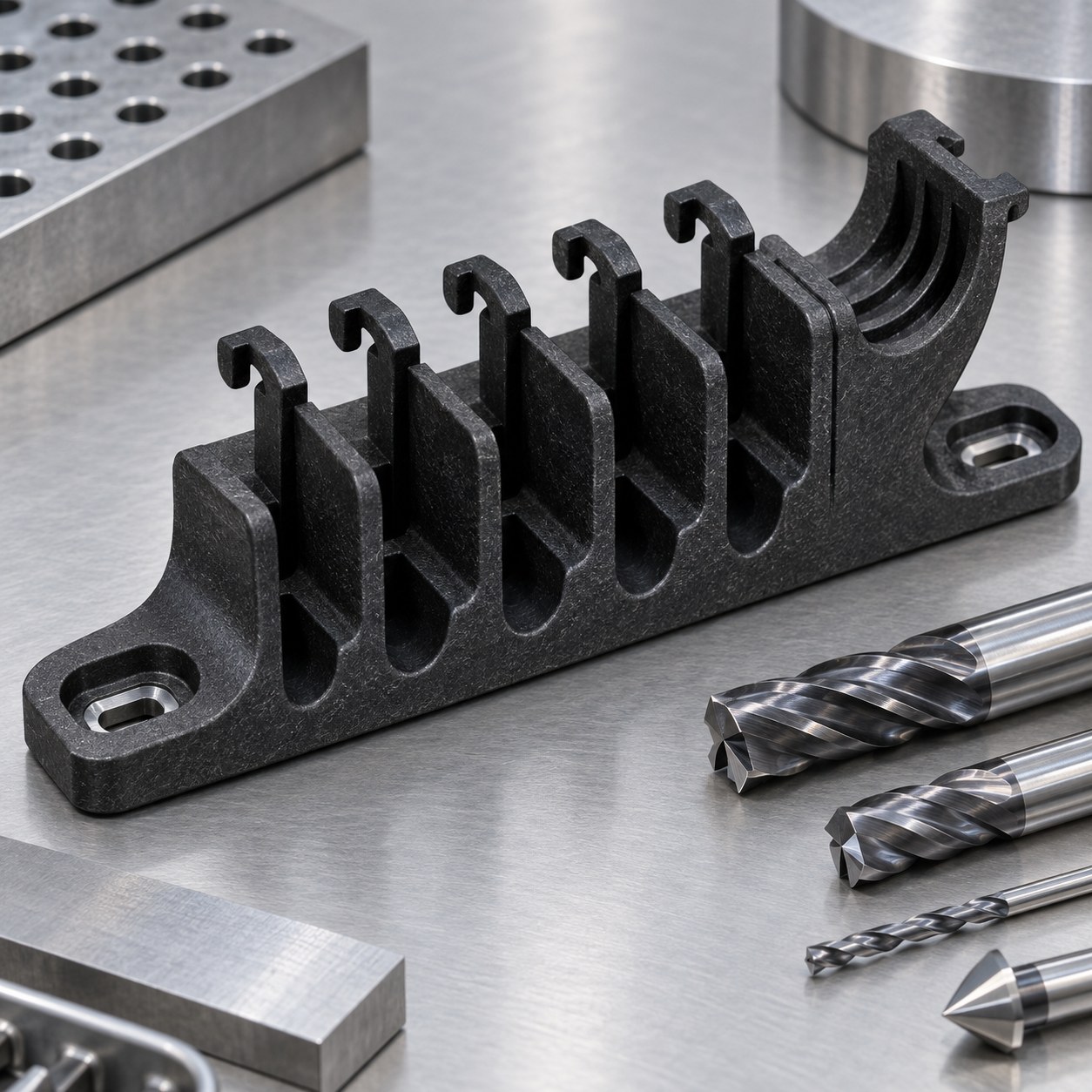
English: PA66-GF30 Cable Guide Tooling for Snap Hooks and Mounting Slots
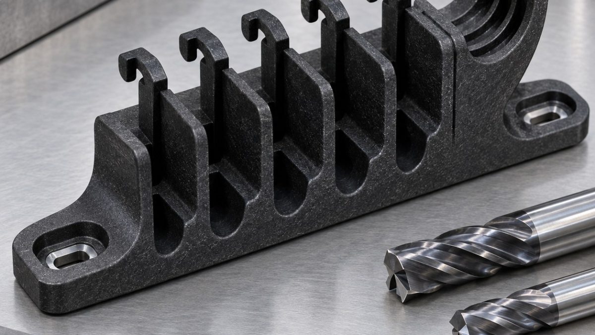
The practical question is how to release several glass-filled nylon snap hooks without chipping their roots or pulling the long base rail out of line. The hypothetical drawing locates all channels from two counterbored mounting slots; hook opening is a free-state requirement. The molded-looking exterior is machined from plate only for this tooling example.
Anchor the slot datums before hook release
Machine the datum face and both mounting slots while the blank is a rigid rectangle. Rough alternate cable channels, leave bridges at every hook tip and finish the strain-relief pocket. Finish hook roots with a fresh micro tool, then remove bridges from the center outward on a full-length vacuum fixture. Chamfer only after the rail is free so burr direction is visible.
Sequence channels, pockets and thin hooks
| Drawing feature | Carbide tool and holder | Why selected / alternative rejected |
|---|---|---|
| Datum face and base rail | 10 mm 2-flute polished diamond-coated carbide end mill, balanced hydraulic holder | Low flute count clears abrasive dust; a many-tooth aluminum cutter recuts fibre debris. |
| Cable channels | 5 mm 2-flute diamond-coated radius end mill, 10 mm reach | Radius matches cable support and reduces fibre breakout; a square corner concentrates root stress. |
| Snap-hook roots and openings | 2 mm single-flute polished diamond-coated end mill, 6 mm reach, precision collet | Single flute evacuates hot dust; a four-flute micro cutter packs the narrow opening. |
| Counterbored mounting slots | 3 mm carbide drill, 4 mm 2-flute end mill and flat-bottom counterbore tool | Interpolation controls slot width; a twist drill alone leaves a conical bearing floor. |
| Strain-relief pocket and chamfers | 6 mm 2-flute radius end mill plus sharp single-flute chamfer mill | Smooth blend avoids a notch; hand scraping feathers glass fibres. |
Manage glass-fibre abrasion and heat
Glass fibre quickly rounds an edge while nylon softens if chips recut. Use approved extraction, keep cutters sharp and reject the micro tool when hook edges turn grey, fuzzy or glossy. Avoid coolant chemistry that changes moisture conditioning. High spindle speed without chip space only melts the matrix.
Check free hook opening and edge quality
Condition the part consistently before dimensional acceptance. Measure slot position from the two datum counterbores, then record each hook opening and return position in the unclamped state. Inspect root radii and channel edges under magnification; functional cable retention requires a separate load test with the intended cable range.
Practical tooling FAQ
Why leave bridges at hook tips?
They keep the thin hooks supported while root geometry and neighboring channels are finished.
Should every edge be hand-deburred?
No. Hand scraping can expose fibres and alter snap geometry; use controlled cutter paths and inspect remaining edges.
glass-filled polymer thin-feature tooling · G10 channel and counterbore selection